Cutting insert

a cutting insert and indexing technology, applied in cutting inserts, turning tools, turning apparatuses, etc., can solve the problems of increasing cutting force and heat dissipation, reducing the protection of cutting corners, and high cutting power use, so as to reduce the contact resistance of rising chips, reduce cutting resistance, and reduce cutting force

Inactive Publication Date: 2006-10-17
PRAMET TOOLS
View PDF13 Cites 33 Cited by
  • Summary
  • Abstract
  • Description
  • Claims
  • Application Information

AI Technical Summary

Benefits of technology

[0007]The cutting insert according to the invention is constructed to lower cutting forces during cutting, owing to a decrease of cutting resistance. This effect is reached by operating with low frictional force between the chip and an area of corner protrusions on the chip face of the upper face. Because the contact area of the chip and the chip face of the upper face is reduced, the contact resistance of rising chips at the upper face, which has the function of chip forming, is reduced, and thereby comes to decrease heat generation at the reduced contact area between the chip and the upper face. A further advantage of the cutting insert according to the present invention is easier breaking of the chip and suitable guidance of outgoing chips, thereby increasing protection of the cutting corners and the cutting edges from outgoing chips, which in total leads to increase of durability of the cutting insert.SUMMARY OF THE INVENTION

Problems solved by technology

These well-known designs of the cutting inserts however require usage of high cutting power to overcome higher frictional force arising at protrusions on the upper face.
At chip breaking with this cutting insert, the chip has undesirably large contact with the spherical area of the protrusion and with a concave rear face, which causes higher frictional forces and thereby increases cutting forces and heat dissipation, such that heat transfers into cutting insert.
One disadvantage of this known solution is decreased protection of the cutting corner since abrasion of the protrusion arises due to friction from chips and deformation and directional change of chip direction during the cutting process caused by the narrow groove, which decreases durability of the cutting insert.

Method used


Image

  • Cutting insert
  • Cutting insert
  • Cutting insert

Examples


Embodiment Construction

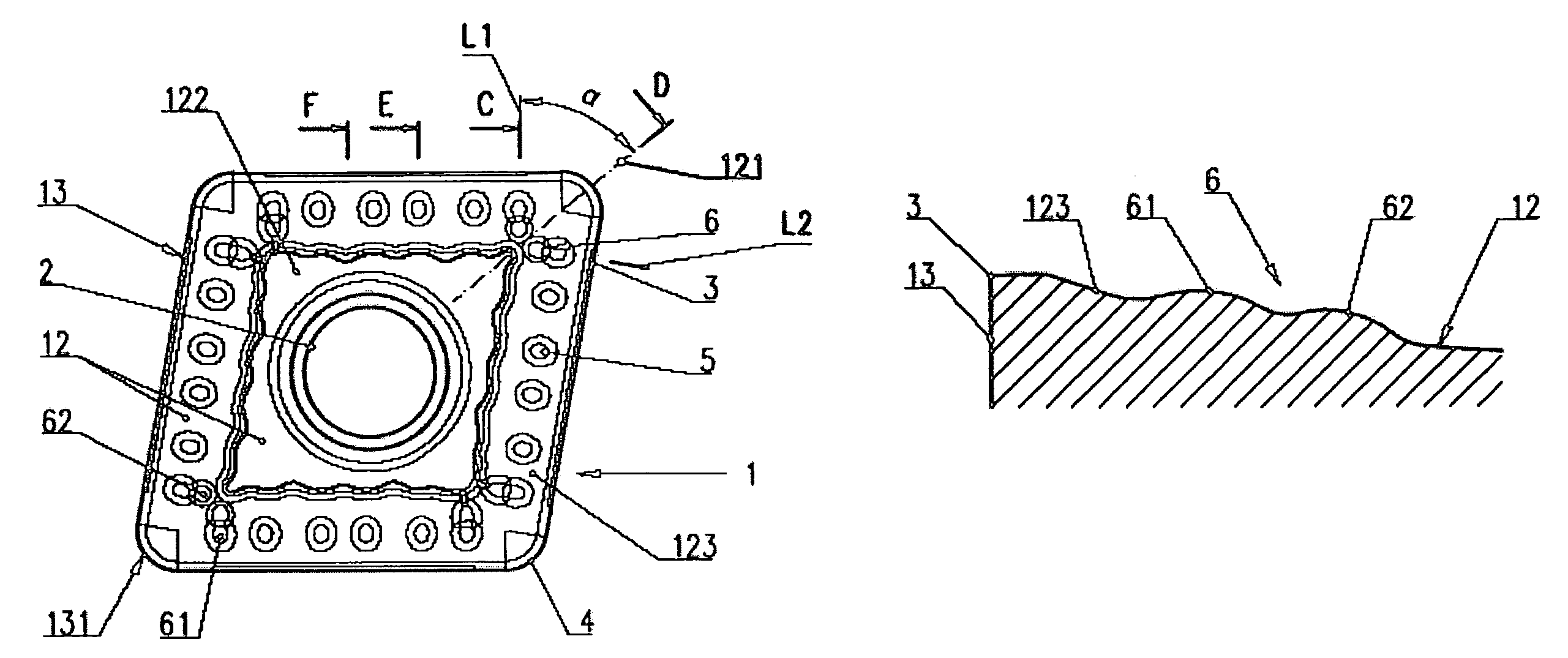
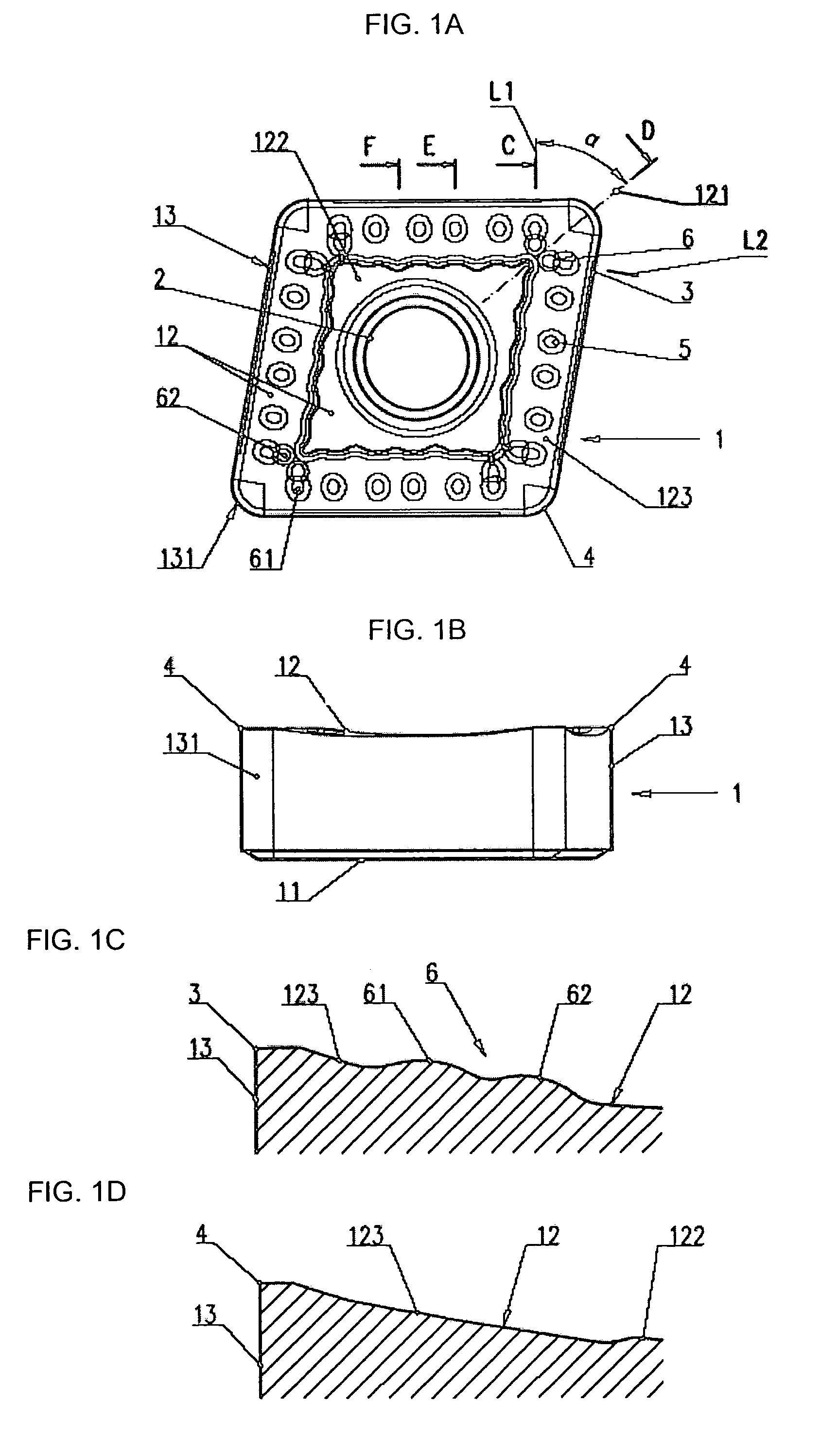
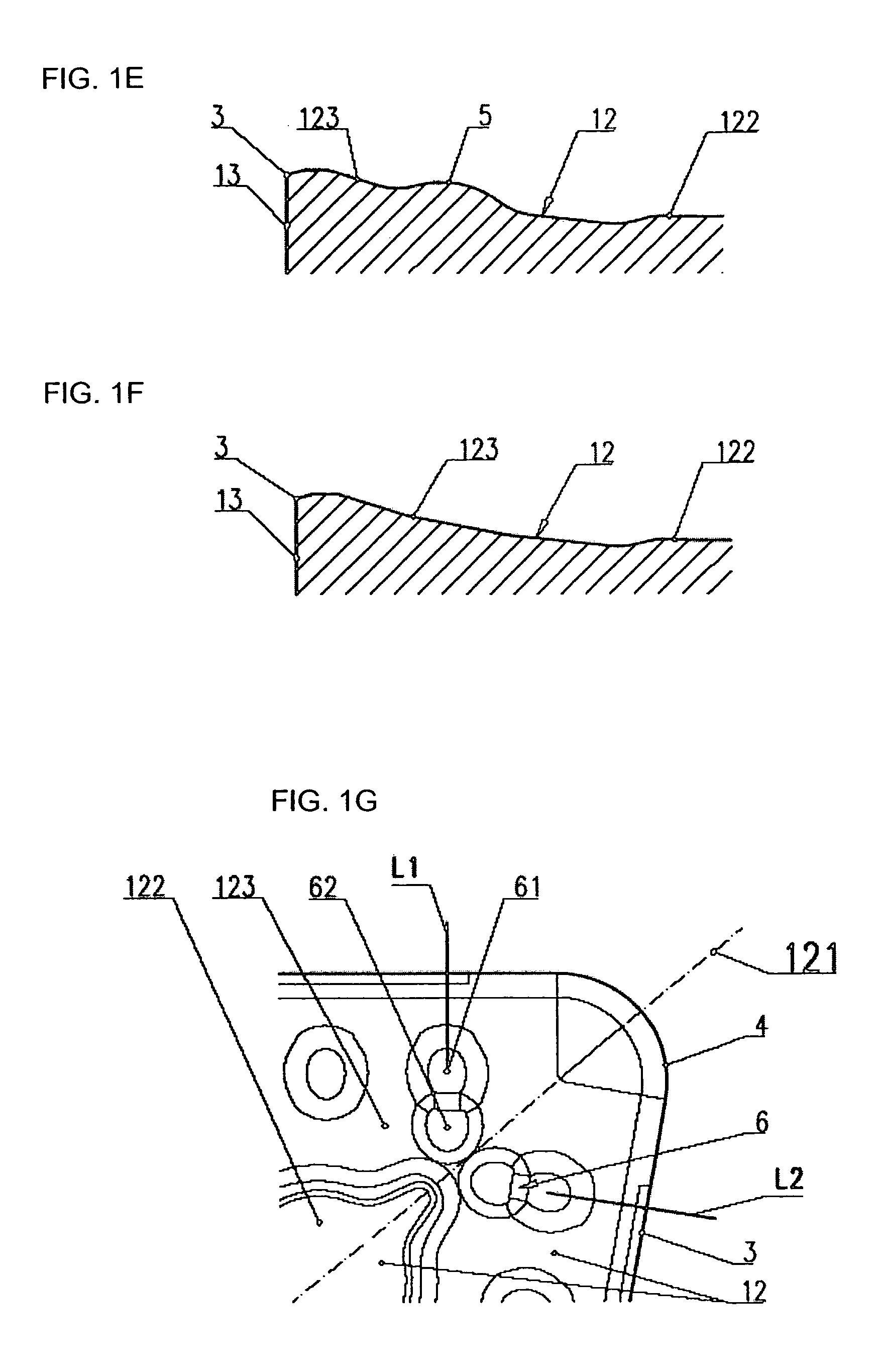
[0031]The cutting insert according to the invention has a polygonal body 1, with a basic shape that is rhombic, as is illustrated in FIG. 1A, or square, as is illustrated in FIG. 2A and which is provided with a centrally positioned clamping opening 2. The body 1 has a lower face 11 and an upper face 12, which are mutually interconnected by peripheral faces 13 containing four rounded corners 131, which are created symmetrically with respect to bisectors 121 of the upper face 12. The upper face 12 contains an essentially smooth or planar mid portion 122, which gradually connects to a chip face 123. The intersections of the chip face 123 of the upper face 12 with the peripheral face 13 create major cutting edges 3 and corner cutting edges 4. Each corner cutting edge 4 is formed symmetrically with regard to the bisector 121 of the corner 131, as illustrated in FIG. 1G.

[0032]Several individual and mutually spaced protrusions 5 are located on the chip face 123 of the upper face 12 alongsi...


PUM

PropertyMeasurementUnit
angleaaaaaaaaaa
areaaaaaaaaaaa
wear resistantaaaaaaaaaa

Abstract

An indexable cutting insert for chip removal machining, the insert having a polygonal body having opposed lower and upper faces that are mutually interconnected by peripheral faces meeting at rounded corners, which are formed symmetrically with respect to upper face bisectors. The upper face includes a mid portion, which is positioned inside of a chip face. Intersections of the chip face and the peripheral face forming major cutting edges and corner cutting edges. The chip face comprises a row of protrusions. A pair of oblong corner protrusions are provided at each corner area of the chip face. The pair is located symmetrically with respect to an associated bisector of the upper face. Each oblong corner protrusion has a longitudinal axis and at least two peak areas. The peak areas are positioned in line, essentially on the longitudinal axis of each oblong corner protrusion.

Description

BACKGROUND OF THE INVENTION[0001]The present invention relates to an indexable cutting insert for chip removal during machining.[0002]Presently, cutting inserts of hard and wear resistant materials are used in tools for chip removal during machining. The geometry of some of these cutting inserts is such as to minimize power requirements for metal cutting operations. At the same time, the geometry of the cutting insert is required to allow chip breaking under a wide range of parameters, for example depth of cut or feed speed. Several cutting inserts comprise upper face protrusions adapted to facilitate the development and breaking of chips. These well-known designs of the cutting inserts however require usage of high cutting power to overcome higher frictional force arising at protrusions on the upper face.[0003]A cutting insert disclosed in U.S. Pat. No. 3,815,192 comprises several protrusions of circular basic shape along the perimeter of the upper face defining zones of chip forma...

Claims


Application Information

Patent Timeline
Patent Type & Authority Patents(United States)
IPC IPC(8): B23B27/16B23B27/14B23B27/22
CPCB23B27/143B23B2200/085B23B2200/321Y10T407/245Y10T407/23Y10T407/235Y10T407/24B23B2200/3618
Inventor KRAHULA PAVELSPA{HACEK OVER (CILOVA JOSEFINA
Owner PRAMET TOOLS
Why Eureka
Try Eureka