Surgical stapling instrument and method thereof

a technology of luminal organs and surgical staples, which is applied in the direction of surgical staples, paper/cardboard containers, blood vessels, etc., can solve the problems of causing intima, inner wall, and causing blood clots in the blood vessel,

Inactive Publication Date: 2006-10-17
HEARTPORT
View PDF156 Cites 238 Cited by
  • Summary
  • Abstract
  • Description
  • Claims
  • Application Information

AI Technical Summary

Benefits of technology

[0013]The present invention provides a novel instrument and method for vascular anastomoses which overcomes the drawbacks of prior art designs and achieves the aforesaid advantages.

Problems solved by technology

The prior art anastomotic stapling instruments form generally circular anastomotic connections, and have been largely limited to alimentary organs.
This unnatural connection may create turbulence in the blood flow as it courses through the anastomosis, damaging the intima (i.e. inner wall) of the blood vessel and predisposing it to forming blood clots.
These techniques are time consuming, not as reliable as stapling, and subject to greater human error than stapling.
Current stapling instruments used for alimentary canal are not suitable, however, for vascular anastomosis due to their large sizes and inability to provide non-circular and low turbulence anastomoses.
An additional drawback of prior stapling instruments is the inability to provide an everted (i.e., folded outwardly) anastomosis.
An inverted vascular anastomosis would expose the cut ends of the blood vessels to the vessel lumen and could lead to the formation of blood clots.

Method used


Image

  • Surgical stapling instrument and method thereof
  • Surgical stapling instrument and method thereof
  • Surgical stapling instrument and method thereof

Examples


Embodiment Construction

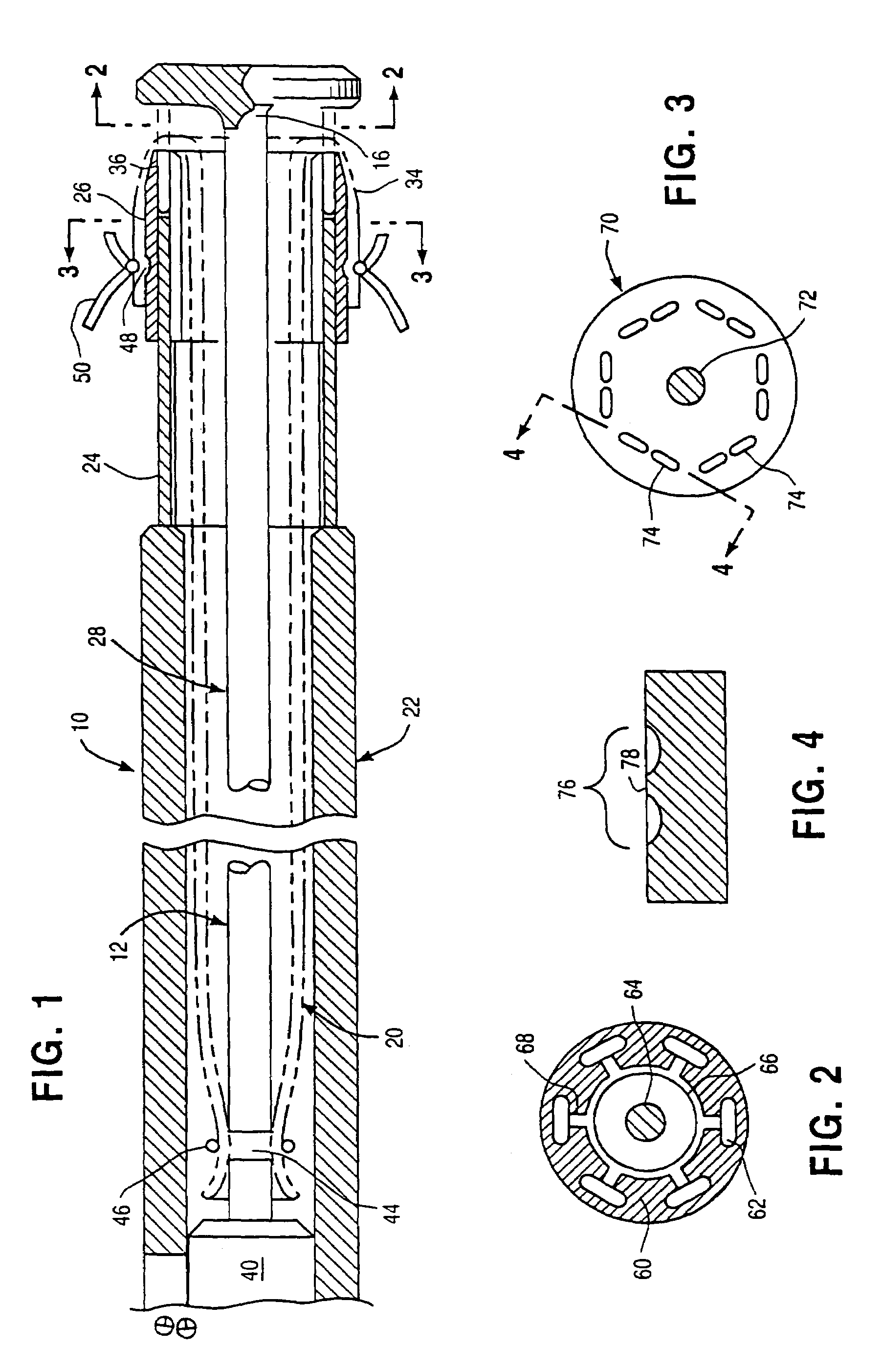
[0048]Referring to FIGS. 1–7, there is shown a structural embodiment of the present invention which is best suited for anastomotic stapling of a tubular vessel having two distal or untethered ends. As will be evidenced by the detailed description below, this embodiment, i.e., distal stapler, is ideal for use during cardiopulmonary bypass surgery for making the primary anastomotic connection of a bypass vein to a coronary artery or to the aorta.

[0049]Referring now to FIG. 1, a portion 10 of the wholly configured distal stapler of the present invention, as shown in FIG. 7, comprises an elongated central rod 12 with anvil 14 mounted at its distal end 16. Anvil 14 is in the form of a circular, elliptical or tear drop-shaped disk and is mounted, by suitable means such as welding, to the end of central rod 12 transversely thereof and at the center of the anvil. The edges of anvil 14 are beveled or otherwise generally rounded to enable anvil 14 to slip easily through incisions in vascular ...


PUM

PropertyMeasurementUnit
circumferencesaaaaaaaaaa

Abstract

A stapler for stapling a tubular structure to another structure. The stapler has an anvil which is expandable from a collapsed position to an expanded position. The stapler has a recess which receives at least a portion of the tubular structure and a shoulder which receives an everted end of the tubular structure. A first actuator moves the anvil relative to the shoulder for compressing the structures which are to be stapled together. A second actuator is used for driving the staples through the structures to be stapled together.

Description

CROSS REFERENCE TO RELATED APPLICATIONS[0001]This application is a continuation U.S. application Ser. No. 10 / 441,447, filed May 20, 2003, now U.S. Pat. No. 6,763,993 which is a continuation of U.S. Application Ser. No. 09 / 776,612, filed Feb. 2, 2001, now issued as U.S. Pat. No. 6,558,643, which is a continuation of U.S. application Ser. No. 09 / 391,297, filed Sep. 7, 1999, now issued as U.S. Pat. No. 6,209,773, which is a continuation of U.S. application Ser. No. 09 / 045,673, filed on Mar. 20, 1998, now issued as U.S. Pat. No. 5,947,363, which is a continuation of U.S. application Ser. No. 08 / 597,691, filed on Feb. 6, 1996, now issued as U.S. Pat. No. 5,732,872, which is a continuation-in-part of U.S. application Ser. No. 08 / 550,285, filed on Oct. 31, 1995, now issued as U.S. Pat. No. 5,709,335, which is a continuation of U.S. application Ser. No. 08 / 261,167, filed Jun. 7, 1994 now abandoned the full disclosures of which are hereby incorporated by reference.FIELD OF THE INVENTION[0002...

Claims


Application Information

Patent Timeline
Patent Type & Authority Patents(United States)
IPC IPC(8): A61B17/068A61B17/00A61B17/064A61B17/08A61B17/11A61B17/115A61F2/06
CPCA61B17/0644A61B17/115A61B17/1152A61B17/1155A61B2017/00243A61B2017/00252A61B2017/081A61B2017/1103A61B2017/1107A61B2017/1135A61F2/064
Inventor BOLDUC, LEE R.HECK, CHRISTOPHER F.
Owner HEARTPORT
Why Eureka
Try Eureka