Method for vacuum deposit on a curved substrate

a vacuum treatment and substrate technology, applied in vacuum evaporation coatings, chemical vapor deposition coatings, coatings, etc., can solve problems such as unsatisfactory iridescence, and achieve the effect of reducing the thickness difference very simply

Inactive Publication Date: 2006-10-17
ESSILOR INT CIE GEN DOPTIQUE
View PDF17 Cites 13 Cited by
  • Summary
  • Abstract
  • Description
  • Claims
  • Application Information

AI Technical Summary

Benefits of technology

[0012]The subject of the present invention is, in a general manner, an arrangement allowing this thickness difference to be reduced very simply.
[0026]In all cases, the results obtained with a mask according to the invention are all the more surprising since, in practice, this mask may advantageously have, with respect to the treated curved substrate, a relatively small extension, which, if desired, makes it possible to limit the overall size of the assembly to that of the curved substrate alone, and which thereby makes it possible, as a corollary, to avoid possible shadowing difficulties.

Problems solved by technology

Should good uniformity of this thickness be lacking, any possible residual reflection runs the risk of resulting in undesirable iridescence.

Method used


Image

  • Method for vacuum deposit on a curved substrate
  • Method for vacuum deposit on a curved substrate
  • Method for vacuum deposit on a curved substrate

Examples


Embodiment Construction

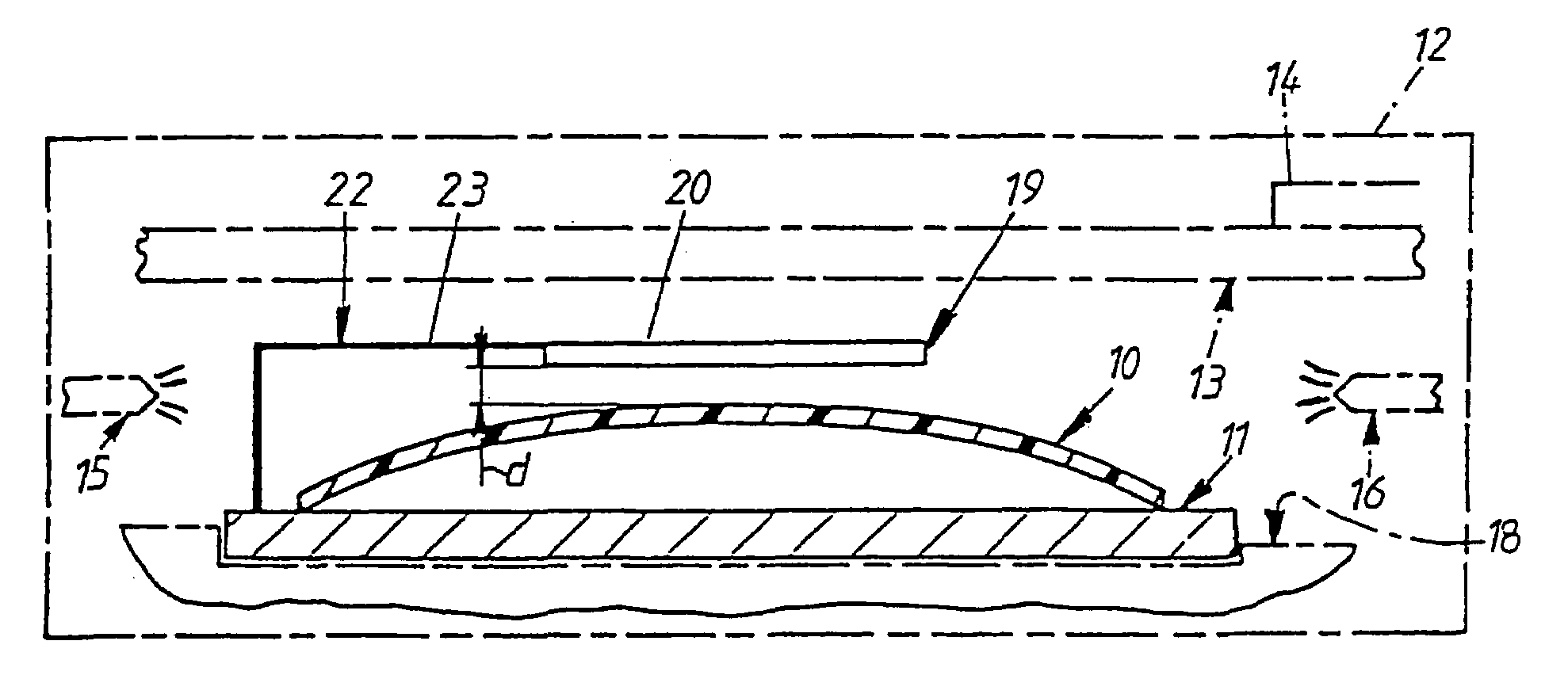
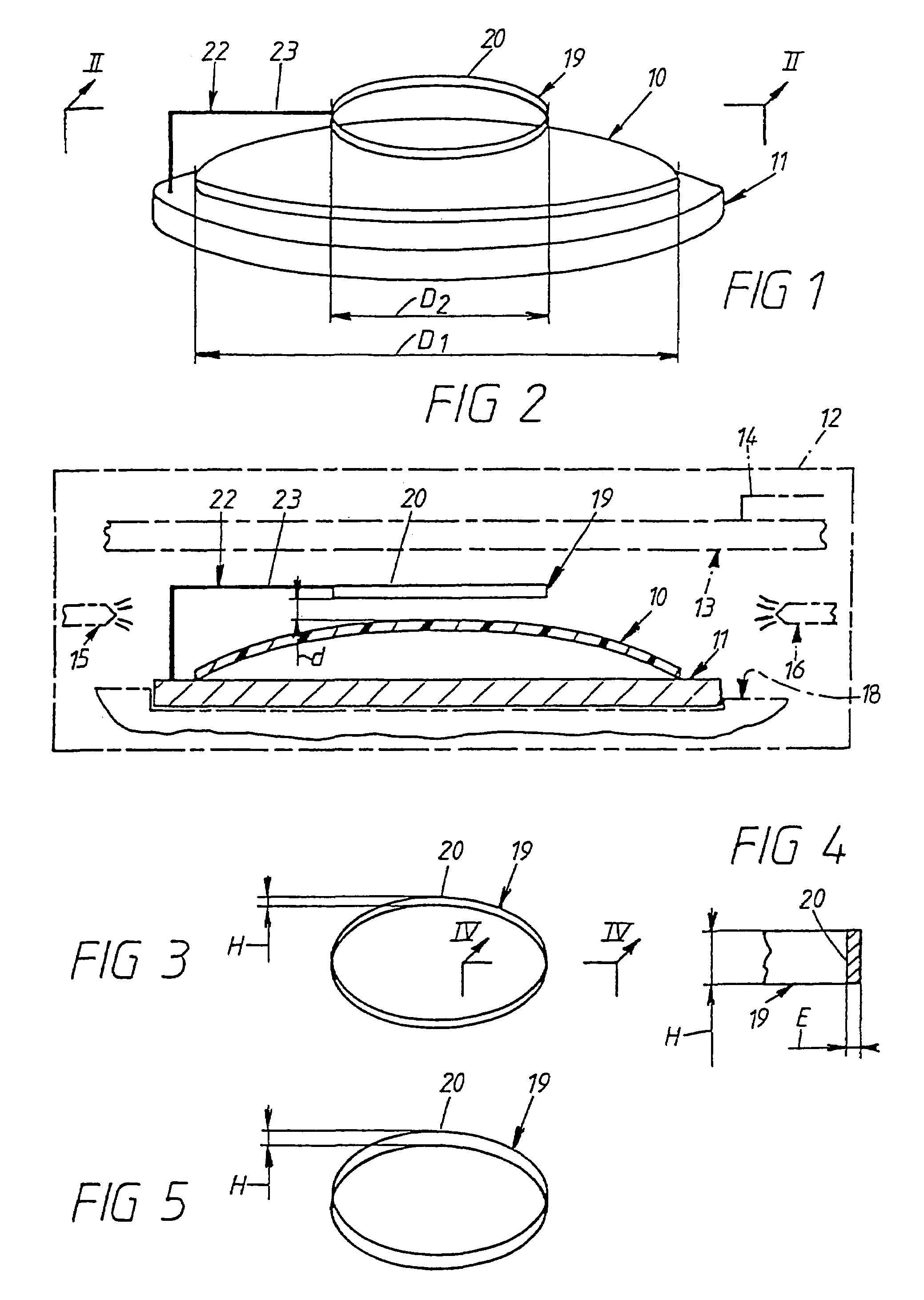
[0037]These figures illustrate, by way of example, the application of the invention to the case in which the curved substrate 10 to be treated is a spectacle lens or, more specifically, a disc of circular contour from which such a spectacle lens is subsequently cut out.

[0038]Let D1 be the diameter of this curved substrate 10 along its contour.

[0039]This diameter D1 is usually between 65 mm and 80 mm.

[0040]In the embodiment illustrated, the curved substrate 10 is, for example, concavo-convex.

[0041]When a vacuum treatment has to be applied to it, such a curved substrate 10 is usually supported, around its periphery, by a support 11 suitable for holding it.

[0042]Since this support 11 is well known per se and does not pertain at all to the present invention, it will not be described here.

[0043]Furthermore, it is also for the sake of convenience that it is illustrated in FIGS. 1 and 2 in the form of a flat disc of circular contour.

[0044]In fact, this support 11 may have very diverse conf...


PUM

PropertyMeasurementUnit
gas pressureaaaaaaaaaa
heightaaaaaaaaaa
diameter D1aaaaaaaaaa

Abstract

The invention concerns a method which consists in a process known per se in producing, on the curved substrate (10) to be treated, a film of material derived from a specific material source (13). The invention is characterized in that it consists in inserting, between the curved substrate (10) and the material source (13), a mask (19) relative to the curved substrate (10), preferably selecting as mask (19), a mask comprising a ring-shaped part (20). The invention is particularly useful for providing lenses with antiglare treatment.

Description

BACKGROUND OF THE INVENTION[0001]The present invention relates in a general manner to the vacuum treatment of any substrate of the kind in which, using a sputtering technique, the deposition of a layer of material coming from a given source of material is carried out, everywhere, in a chamber, on this substrate by subjecting, for example, this source of material, which then serves as a cathode, to a suitable ion bombardment, the result of which is that particles are torn off it and these are then deposited on the substrate.[0002]The invention is aimed more particularly at the case in which the treated substrate is a curved substrate, or even a highly curved substrate, as is the case, at least, in certain spectacle lenses, particularly those of high power.[0003]The expression “curved substrate” should therefore be understood to mean here, more generally, a substrate which, in the manner of a spectacle lens, has a curvature accentuated to a greater or lesser extent in at least one tra...

Claims


Application Information

Patent Timeline
Patent Type & Authority Patents(United States)
IPC IPC(8): B05D1/32C23C14/04C23C14/24
CPCC23C14/044
Inventor COMBLE, PASCALKELLER, GERHARDMOUHOT, FREDERIC
Owner ESSILOR INT CIE GEN DOPTIQUE
Why Eureka
Try Eureka