Quantum well energizing method and apparatus

a quantum well and energizing technology, applied in semiconductor lasers, fluid couplings, batteries, etc., can solve the problems of inability to economically incorporate quantum wells into devices, low efficiency, and low efficiency, and achieve the effect of improving the efficiency of the disclosed method and apparatus, facilitating the conversion of hot electron energy, and facilitating the transfer of captured phonons

Active Publication Date: 2006-10-17
NEOKISMET L L C
View PDF84 Cites 16 Cited by
  • Summary
  • Abstract
  • Description
  • Claims
  • Application Information

AI Technical Summary

Benefits of technology

[0005]The disclosed method and apparatus utilizes a chemical reaction as a primary energy source to energize a quantum well structure. Chemical reactions that occur on or near a surface of a conductor or catalyst will emit hot electrons and hot phonons into the catalyst. It has been determined that a substantial fraction of the energy released during certain chemical reactions can be directly transferred into an adjacent quantum well structure before that energy is converted into heat. This transfer of energy utilizes two modes: hot electrons and hot phonons. Both of these energy transfer modes are effective to pump or energize the quantum wells. The disclosed method and apparatus utilizes a structure that is a combination of a catalyst layer and an interface layer that are disposed adjacent to a quantum well device. The catalyst layer catalyzes a chemical reaction on its upper surface and...

Problems solved by technology

Although it is usually preferable to use as many quantum wells in a quantum well layer as possible, the cost of fabrication can limit the number of quantum well that can be economically incorporated into the device.
One problem associated with existing quan...

Method used


Image

  • Quantum well energizing method and apparatus
  • Quantum well energizing method and apparatus
  • Quantum well energizing method and apparatus

Examples


Embodiment Construction

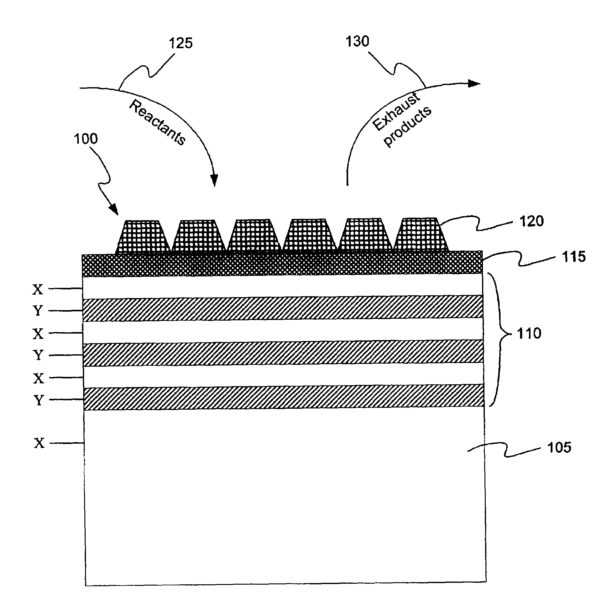
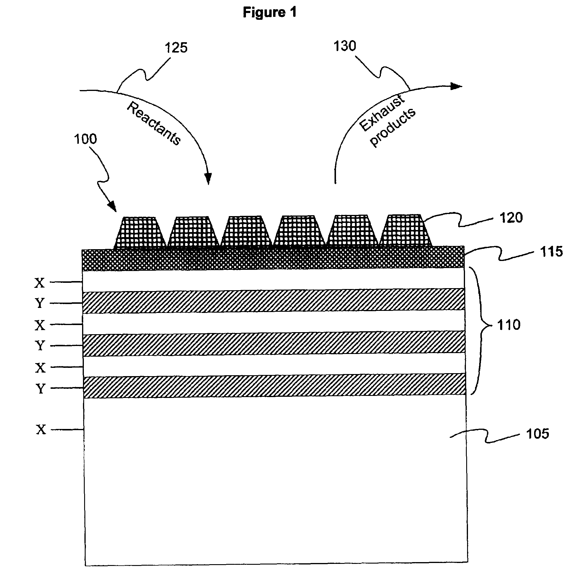
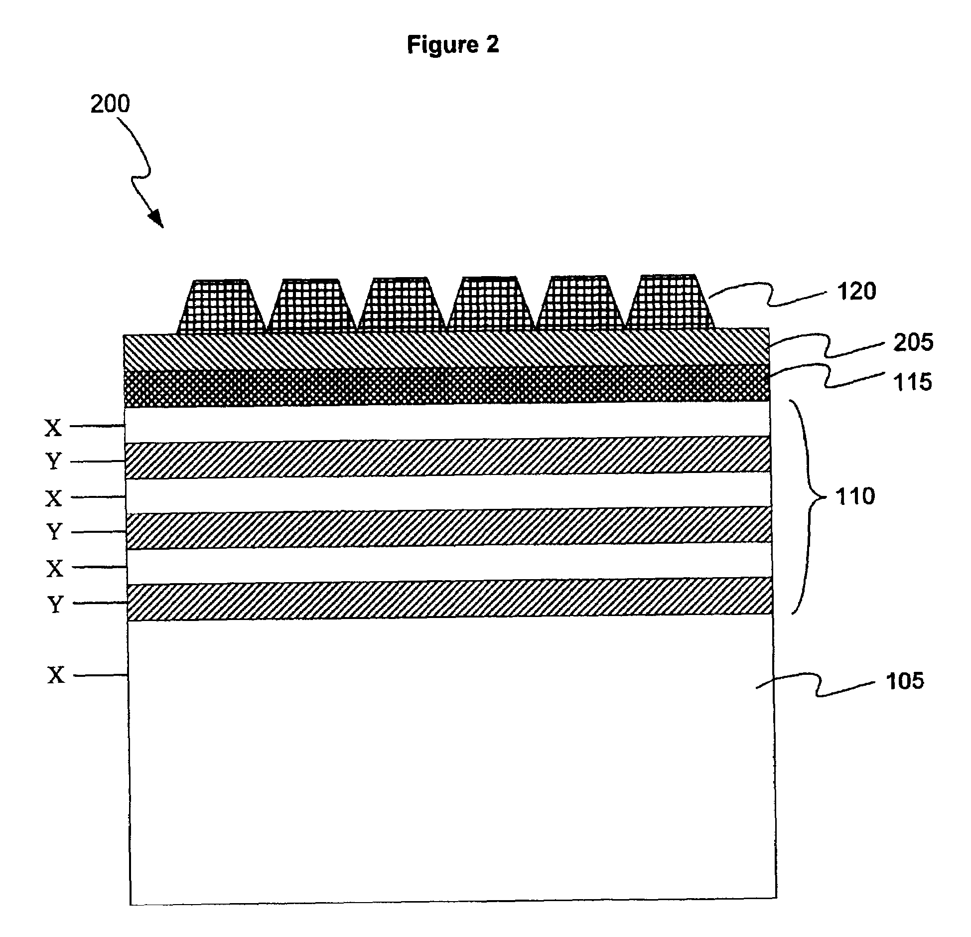
[0014]The disclosed method and apparatus relates to a structure for catalyzing a chemical reaction to provide hot electrons and hot phonons to energize a quantum well structure. Chemical reactions that occur on or near a surface, such as a conductor or catalyst, will emit hot electrons and hot phonons into the catalyst. It has been determined that a substantial fraction of the energy released during certain chemical reactions can be directly transferred into a quantum well structure before that energy is converted into heat. Our theoretical models have indicated that a majority of the energy produced by a chemical reaction can be used to energize a quantum well, depending upon the specific device characteristics. The transfer of energy from the chemical reaction to the quantum well utilizes two transfer modes: hot electrons and hot phonons. Both of these energy transfer modes are effective to pump or energize the quantum wells with charge carriers.

[0015]The disclosed apparatus and m...


PUM


Abstract

A method and apparatus that converts energy provided by a chemical reaction into energy for charging a quantum well device. The disclosed apparatus comprises a catalyst layer that catalyzes a chemical reaction and captures hot electrons and hot phonons generated by the chemical reaction, and an interface layer placed between the catalyst layer and a quantum well. The interface layer facilitates the transfer of hot electrons and hot phonons from the catalyst layer into the quantum well layer. The interface layer can also convert hot electrons into hot phonons, and vice versa, depending upon the needs of the particular quantum well device. Because the hot electrons and the hot phonons are unstable and readily degrade into heat energy, the dimensions of the catalyst layer and the interface layer are very small. To improve the efficiency of the transfer of hot electrons and hot phonons to the quantum well, other interface layers, such as a catalyst interlayer and a catalyst interface, may be utilized.

Description

CROSS REFERENCE TO RELATED APPLICATION(S)[0001]This application claims priority to U.S. provisional patent application No. 60 / 302,274 entitled “Quantum Well Energizer,” which was filed on Jun. 29, 2001 and is hereby incorporated by reference. This application also relates to U.S. Pat. No. 6,114,620 entitled “Pre-Equilibrium Chemical Reaction Energy Converter,” which was filed on May 4, 1999 and is hereby incorporated by reference.BACKGROUND[0002]Quantum wells are solid state electronic devices that are well known in the art. Among other things, quantum wells can be used to form light emitting diodes (LEDs), semiconductor lasers, and other tunneling devices. An representative example of a quantum well structure is depicted in FIG. 7. In FIG. 7, a quantum well structure 700 is depicted as comprising a substrate 705 and a plurality of alternating layers 710, (X and Y). Each of these alternating layers, X and Y, comprises a different composition of semiconductor material, thereby creati...

Claims


Application Information

Patent Timeline
IPC IPC(8): H01L31/058H01L31/06H01L29/15H01L31/00H01L31/0304H01L33/06H01L49/00H01S5/04H01S5/343
CPCB82Y20/00H01L29/155H01L31/0352H01L33/06H01S5/04H01S5/34333H01L31/0304H01S2301/173Y10S136/291
Inventor ZUPPERO, ANTHONY C.GIDWANI, JAWAHAR M.
Owner NEOKISMET L L C
Why Eureka
Try Eureka