Charged-particle beam accelerator, particle beam radiation therapy system using the charged-particle beam accelerator, and method of operating the particle beam radiation therapy system

a radiation therapy system and accelerator technology, applied in accelerators, electric discharge tubes, electrical devices, etc., can solve the problems of system becoming considerably costly, rf-ko is not disclosed in the publication, and the reliability of equipment is not known, so as to achieve efficient irradiation and reduce unwanted dose

Active Publication Date: 2006-10-17
MITSUBISHI ELECTRIC CORP
View PDF12 Cites 163 Cited by
  • Summary
  • Abstract
  • Description
  • Claims
  • Application Information

AI Technical Summary

Benefits of technology

[0048]As the high-frequency electric field is used only for spreading the beam, only one RF-KO unit (radio frequency generating unit) 8 is required for beam extraction. Since the number of betatron oscillations per circulation differs from one particle to another and from one amplitude to another, there exist many orbiting particles which can not be taken out with a single-frequency electric field. Therefore, it is desirable to apply a conventionally used frequency-modulated high-frequency electric field, wherein the modulation factor should be set to a value at which the beam is not directly extracted but the particles orbiting near the center of the separatrix are spread outward. Application of a conventionally used frequency-modulated high-frequency electric field is also effective. The RF-KO unit 8 of the embodiment produces similar advantageous effects on high-frequency magnetic fields as well.
[0049]The extracted particle beam is guided to the treatment room through the beam transport line 300 and projected on the patient 30 through the beam delivery unit 17. The beam delivery unit 17 includes parallel scanning electromagnets 21 for targeting the beam to desired locations, a dose monitor, a beam position monitor and a range shifter 22 for varying the beam energy.
[0050]Here, an example of a treatment by spot-scanning irradiation is described with reference to FIG. 5 which illustrates part of internal components of the beam delivery unit 17. Using upstream and downstream parallel scanning electromagnets 21 for linearly moving the beam position, the beam delivery unit 17 can direct the beam to desired irradiation spots along a radial direction of a target area by a parallel scanning method. The beam delivery unit 17 can target the beam to desired irradiation spots in a two-dimensional plane by rotating the upstream and downstream parallel scanning electromagnets 21 by the same angle. The number of irradiation spots in one radial scanning direction is 3 or so on average in practical applications and the scanning electromagnets 21 can be rotated in approximately 50 steps to irradiate the target area with a uniform dose distribution. The beam is controlled to aim at different target depths by varying the thickness of the range shifter 22. Among these three kinds of adjustments, i.e., beam orientation along the linear (radial) scanning direction, rotation of the scanning electromagnets 21 and irradiation depth control, what is most time-consuming is the rotation of the scanning electromagnets 21 which takes up about 500 ms.
[0051]A few tens of milliseconds is needed for varying magnetic fields generated by the scanning electromagnets 21 and the range shifter 22 requires a switching time of approximately 30 ms for changing its thickness. Accordingly, the spot-scanning irradiation is executed as follows. Specifically, the scanning electromagnets 21 direct the beam axis to a first irradiation spot by moving the beam axis along the radial scanning direction as necessary. Next, the range shifter 22 sets the beam to target a desired irradiation depth (target depth). Then, the scanning electromagnets 21 direct the beam axis to a next irradiation spot by moving the beam axis along the radial scanning direction and the range shifter 22 switches its thickness for a next irradiation depth. This sequence is repeatedly executed as many times as necessary. When all irradiation spots taken along one radial scanning direction have been irradiated at all target depths with the particle beam, the scanning electromagnets 21 are rotated to emit the beam against irradiation spots taken along a next radial scanning direction. Irradiation time per spot ranges from a few milliseconds to a few tens of milliseconds. The particle beam is extracted from the synchrotron 200 and ejected through the beam delivery unit 17 when all preparatory operations for radiating the beam against each irradiation spot have been completed. As the total number of irradiation spots could reach a few thousands or more, it is needed to extract the beam from the synchrotron 200 as soon as the preparatory operations for irradiation have been completed.
[0052]FIGS. 6A to 6F are diagrams showing an example of an operating procedure of the synchrotron 200. When the preparatory operations for irradiating one target irradiation spot have been completed (FIG. 6A), an overall controller outputs an extraction start signal (FIG. 6B) Upon receiving the extraction start signal, the extraction quadrupole electromagnet unit 9 generates a magnetic field (FIG. 6D). Then, the particle beam is extracted from the synchrotron 200 and ejected through the beam delivery unit 17 (FIG. 6E) and the dose monitor of the beam delivery unit 17 begins to measure the value of dose. The dose monitor outputs a dose complete signal at a point in time where irradiation has reached a prescribed dose (FIG. 6C). Upon receiving the dose complete signal, the extraction quadrupole electromagnet unit 9 stops generating the magnetic field. Subsequently, the RF-KO unit 8 produces a high-frequency electric field (FIG. 6F) to spread the circulating beam outward up to the proximity of the boundary of the separatrix. At the same time, the beam delivery unit 17 performs the preparatory operations for irradiating a next target irradiation spot. When the preparatory operations have been completed, the particle beam is extracted from the synchrotron 200 and ejected through the beam delivery unit 17 again by the same operating procedure as explained above.
[0053]When irradiating an organ which greatly moves due to respiration of the patient 30, such as a lung or liver, the beam is ejected when the organ is relatively stabilized during an exhaling period. This approach helps reduce unwanted dose to any normal (unaffected) tissues. One method for achieving efficient irradiation is to detect target area displacements of the abdomen of patient 30 due to respiration by using the target displacement sensor 31 which can remotely detect displacements of an abdominal part where an irradiation target exists and to emit the beam when the level of a signal output from the target displacement sensor 31 falls within a preset range. An irradiation enable signal shown in FIG. 6A is a signal which is output when the output signal level of the target displacement sensor 31 falls within the preset range. Although the irradiation enable signal is actually a long pulse signal which typically lasts for about 1 to 2 seconds, the signal is depicted as a short pulse signal in FIG. 6A to allow for easy recognition of a relationship with the other signals. The extraction quadrupole electromagnet unit 9 generates the magnetic field only when the irradiation enable signal is in an ON state and the extraction start signal is produced.

Problems solved by technology

Although this Patent Publication proposes a beam extraction method for extracting a charged-particle beam from an accelerator by applying a high-frequency electromagnetic field to the circulating beam to increase the amplitude of betatron oscillation, the Publication does not disclose any practical method of frequency control for radio frequency knockout (RF-KO).
This requires a complicated control system which results in an expensive beam radiation system, also causing a problem concerning equipment reliability which is most important for medical systems.
Therefore, optimization of the parameters at construction and adjustment of the charged-particle beam radiation system is so time-consuming that the system becomes considerably costly.
If the stability of the power supply is lowered for the sake of cost reduction, however, resultant fluctuation in power supply voltage will cause limits of a stability region to fluctuate.
Therefore, even if the charged-particle beam radiation system is entirely turned off, a beam will be emitted afterwards due to the power supply voltage fluctuation and this poses a serious problem.

Method used


Image

  • Charged-particle beam accelerator, particle beam radiation therapy system using the charged-particle beam accelerator, and method of operating the particle beam radiation therapy system
  • Charged-particle beam accelerator, particle beam radiation therapy system using the charged-particle beam accelerator, and method of operating the particle beam radiation therapy system
  • Charged-particle beam accelerator, particle beam radiation therapy system using the charged-particle beam accelerator, and method of operating the particle beam radiation therapy system

Examples


first embodiment

[0037]A first embodiment of the invention is now described with reference to the accompanying drawings.

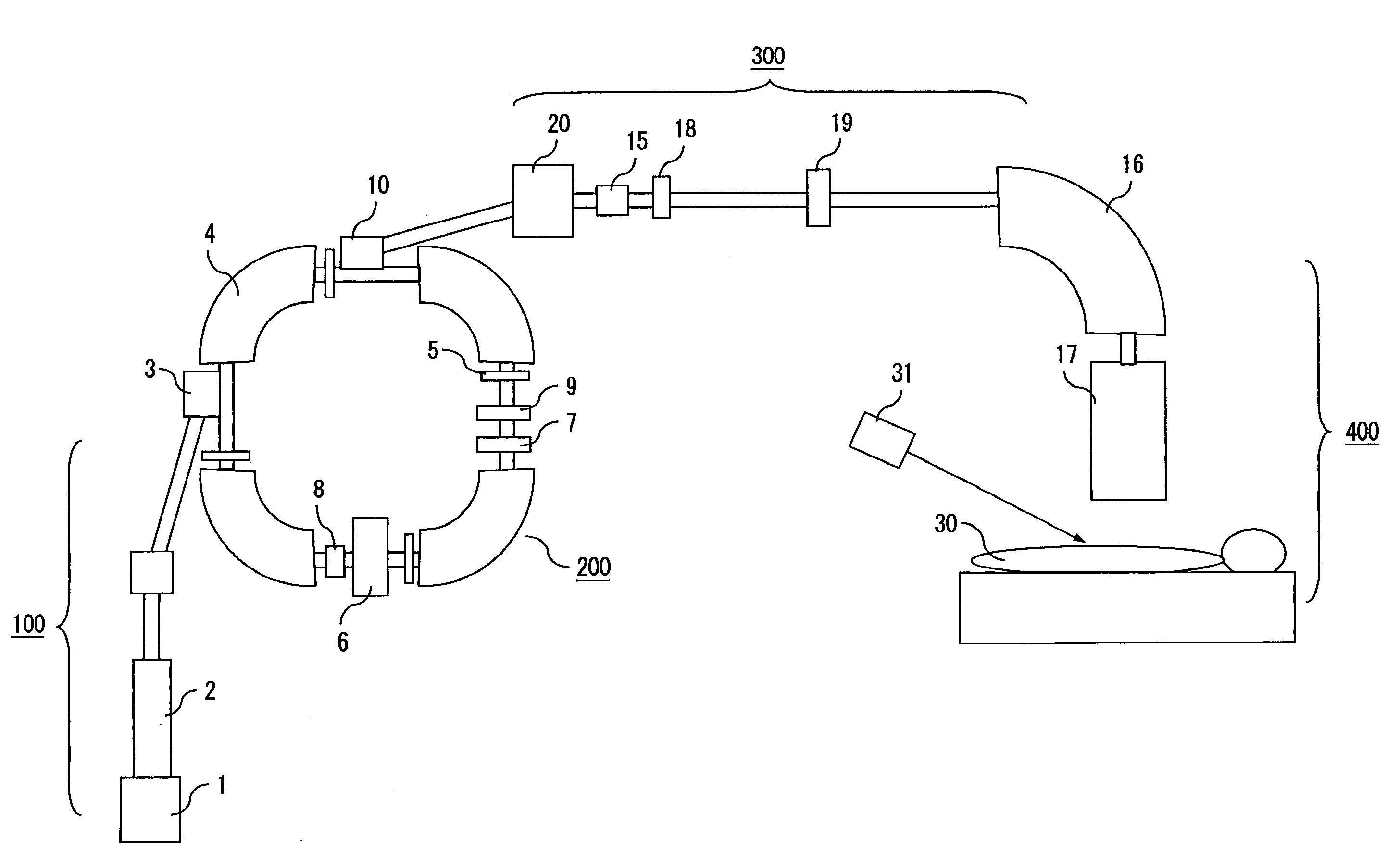
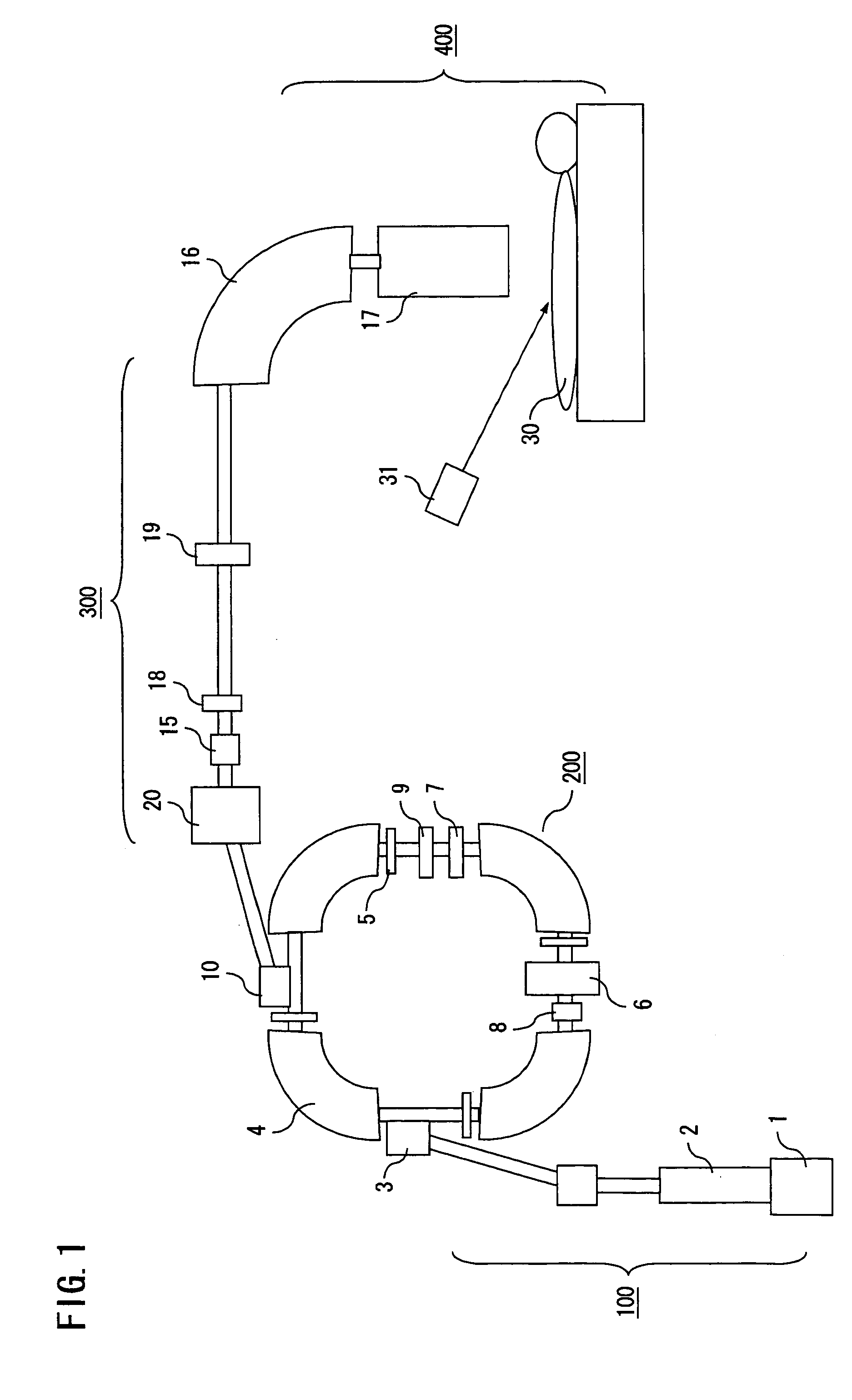
[0038]FIG. 1 is a diagram schematically showing a particle beam radiation system in which a charged-particle beam accelerator 200 and a particle beam radiation therapy system are combined. Referring to this Figure, the charged-particle beam accelerator 200 includes an injection septum 3, four main bending electromagnet units 4, four main quadrupole electromagnet units 5, a high-frequency acceleration unit 6, a sextupole electromagnet unit 7, an RF-KO unit 8 constituting a high-frequency generator, an extraction quadrupole electromagnet unit 9 and an extraction septum 10. The particle beam radiation system includes a beam injection apparatus 100 provided in an upstream stage of the charged-particle beam accelerator 200 for injecting a low-energy beam thereinto. The beam injection apparatus 100 includes an ion source 1 and a linear accelerator 2.

[0039]A charged-particle beam extracte...

second embodiment

[0059]A second embodiment of the invention is now described. While the RF-KO unit (radio frequency generating unit) 8 is turned off when the extraction quadrupole electromagnet unit 9 is activated in the foregoing first embodiment as can be seen from FIGS. 6D and 6F, the same advantageous effects as explained above with reference to the first embodiment can be obtained even if the radio frequency generating unit 8 is of a type which generates a frequency-modulated (FM) signal of which frequency is varied over a range of f1 to f2 and is continuously operated as depicted in FIG. 8F. Also, if two such radio frequency generating units 8 are used as in prior art examples to generate FM signals of which phases are offset from each other as shown in FIGS. 9F and 9G, it becomes possible to extract particles more efficiently. The same advantageous effects can also be obtained even if the radio frequency generating unit 8 is of a type which continuously generates a signal containing frequency...

third embodiment

[0065]A third embodiment of the invention is now described. It is advantageous to install the beam blocking electromagnet unit 18 for generating a magnetic field only during a period between the extraction start signal (FIG. 6B) and the dose complete signal (FIG. 6C) in the beam transport line 300 as shown in FIG. 1 so that no particle beam would be transported to the beam delivery unit 17 even when the beam is extracted at a point in time not between the extraction start signal (FIG. 6B) and the dose complete signal (FIG. 6C) due to noise generated by any of power supplies of the main bending electromagnet units 4, the main quadrupole electromagnet units 5 or the RF-KO unit 8, for example.

[0066]FIG. 11G shows an operating pattern of the beam blocking electromagnet unit 18. In this embodiment, the bending electromagnet unit 20 disposed in the beam transport line 300 is set to bend the beam by a smaller angle so that the beam deviates from a central axis of a normal beam path and col...


PUM


Abstract

A charged-particle beam accelerator includes an RF-KO unit for increasing the amplitude of betatron oscillation of a charged-particle beam within a stable region of resonance and an extraction quadrupole electromagnet unit for varying the stable region of resonance. The RF-KO unit is operated within a frequency range in which the circulating beam does not go beyond a boundary of the stable region of resonance, and the extraction quadrupole electromagnet unit is operated with appropriate timing as required for beam extraction so that the charged-particle beam is extracted with desired timing.

Description

BACKGROUND OF THE INVENTION[0001]1. Field of the Invention[0002]The present invention relates to a charged-particle beam accelerator which emits a high-energy particle beam produced by accelerating along a circulating orbit a low-energy beam introduced from an ion source, as well as a particle beam radiation therapy system employing such a charged-particle beam accelerator and a method of operating the particle beam radiation therapy system.[0003]2. Description of the Background Art[0004]Conventionally, charged-particle beams produced by circular accelerators like a synchrotron are used for physical experiments and medical applications. The circular accelerator generates a particle beam by accelerating charged particles along a circulating orbit. The charged-particle beam is taken out of the circulating orbit and delivered to a location where the beam is used for a physical experiment or medical treatment through a beam transport line. In one beam extraction technique employed in th...

Claims


Application Information

Patent Timeline
Patent Type & Authority Patents(United States)
IPC IPC(8): H01J23/00A61N5/10G21K5/04H05H7/00H05H7/06H05H7/10H05H13/04
CPCG21K5/04H05H7/06H05H7/10
Inventor NAKANISHI, TETSUYAYOSHIDA, KATSUHISAIKEDA, MASAHIRO
Owner MITSUBISHI ELECTRIC CORP
Why Eureka
Try Eureka