Motor driving apparatus and motor driving method

a technology of motor driving and motor stops, which is applied in the direction of motor/generator/converter stoppers, electronic commutators, dynamo-electric converter control, etc., can solve the problems of loss of synchronism and reverse rotation, oscillation, loss of detection errors, etc., and achieve stable sensor-less starting, shortening the period of time, and simple apparatus structure

Inactive Publication Date: 2006-10-17
COLLABO INNOVATIONS INC
View PDF18 Cites 36 Cited by
  • Summary
  • Abstract
  • Description
  • Claims
  • Application Information

AI Technical Summary

Benefits of technology

[0017]The present invention has been devised to solve the above-mentioned problems, and has its objective to provide a driving apparatus and a method which can achieve stable sensor-less starting without a starting failure, that is, which can shorten a period of time required for judging the relative initial position of the rotor to the stator and achieve a simple structure of the apparatus.
[0018]A motor driving apparatus according to the present invention is an apparatus which drives a motor having windings of a plurality of phases and a rotor in a sensor-less control. The motor driving apparatus includes a comparator operable to compare an induced voltage generated in a motor winding of a non-conduction phase with a predetermined threshold, a threshold controller operable to control the threshold; a position determining unit operable to determine a rotor position based on an output from the comparator, a phase-switching controller operable to switch a conduction phase in response to the rotor position; and a current output unit operable to generate a current used for driving the motor and to supply the current to the conduction phase. While the rotor is stopped, the phase-switching controller supplies a predetermined phase of winding with a current pulse having a predetermined pulse width so as not to cause the rotor to react and operate in order to determine the initial position of the rotor. The position determining unit determines an initial position of the rotor based on the result of comparison between the induced voltage generated in a non-conduction phase by the current pulse and the threshold. The phase-switching controller performs energization (or commutation) according to the determined initial position of the rotor to start up the motor.
[0019]This arrangement allows the initial position of the rotor to be determined quickly, consequently providing a stable starting operation. It also make it possible to start supplying a current to an appropriate phase at an earlier timing at start up, consequently reducing a period required for achieving a desired rotation speed.
[0020]In accordance with the present invention, the rotor initial position can be detected in a short time, and a stable sensor-less starting operation is carried out without a starting failure; thus, it becomes possible to shorten a period of time required for starting by using a simple structure.

Problems solved by technology

In this method, however, since no back electromotive force is generated unless the motor is rotating, the back electromotive force is not detected at the time of starting the motor, with the result that a starting failure, such as oscillation, loss of synchronism and reverse rotation, tends to occur depending on the initial position of the rotor.
In the control system proposed in Japanese Patent No. 2547778, since the highest amplitude value is varied dependent on production deviations among the windings of the stator, a detection error tends to occur due to slight deviations in the windings.
Consequently, a starting failure, such as oscillation, loss of synchronism and reverse rotation, tends to occur.
Moreover, since the rotor initial position is judged based on combinations of polarities of the sum of induced voltages of the respective phase windings, it is necessary to refer to a table or the like relating to the combinations, which makes the structure of the device more complicated.

Method used


Image

  • Motor driving apparatus and motor driving method
  • Motor driving apparatus and motor driving method
  • Motor driving apparatus and motor driving method

Examples


embodiment 1

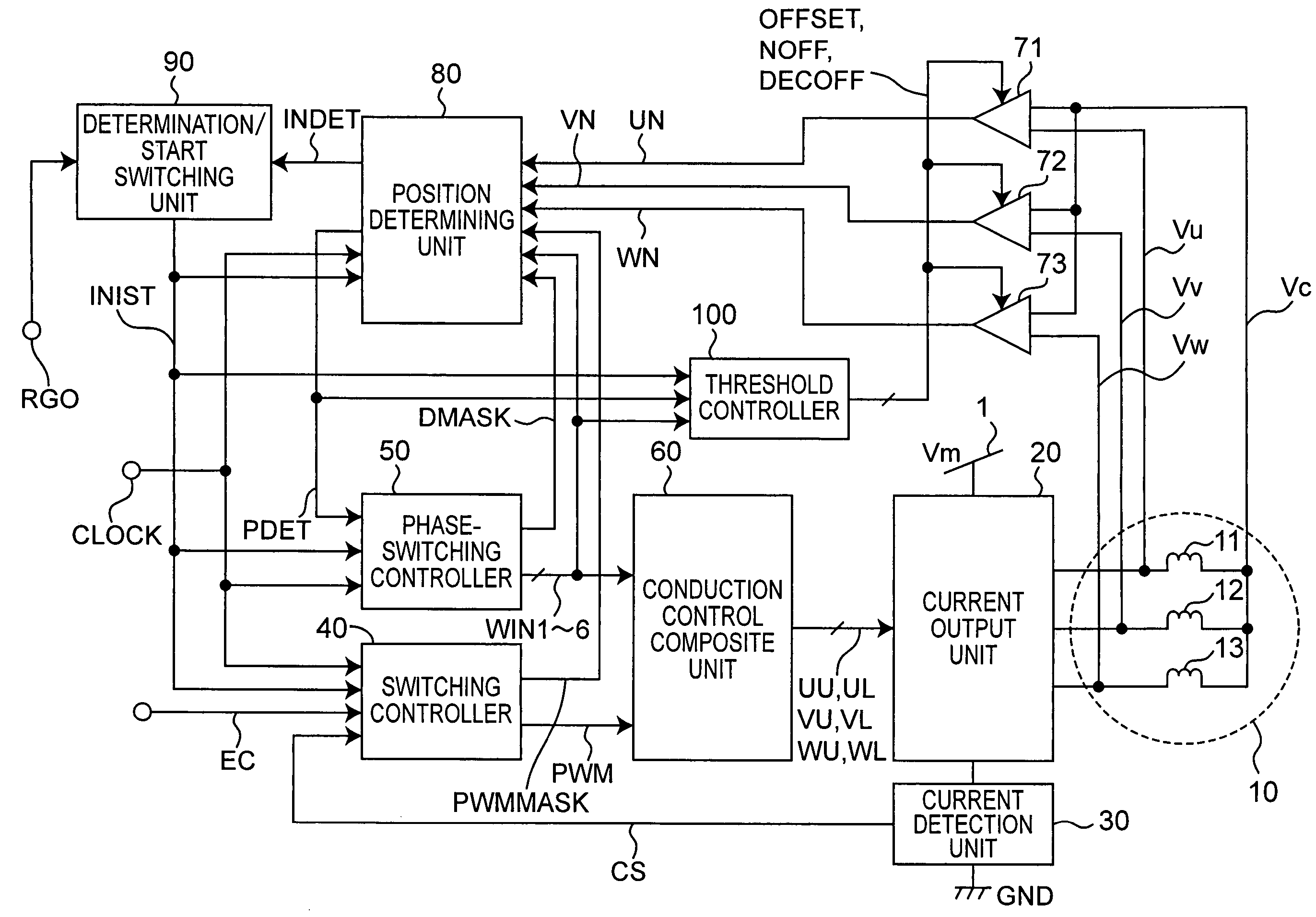
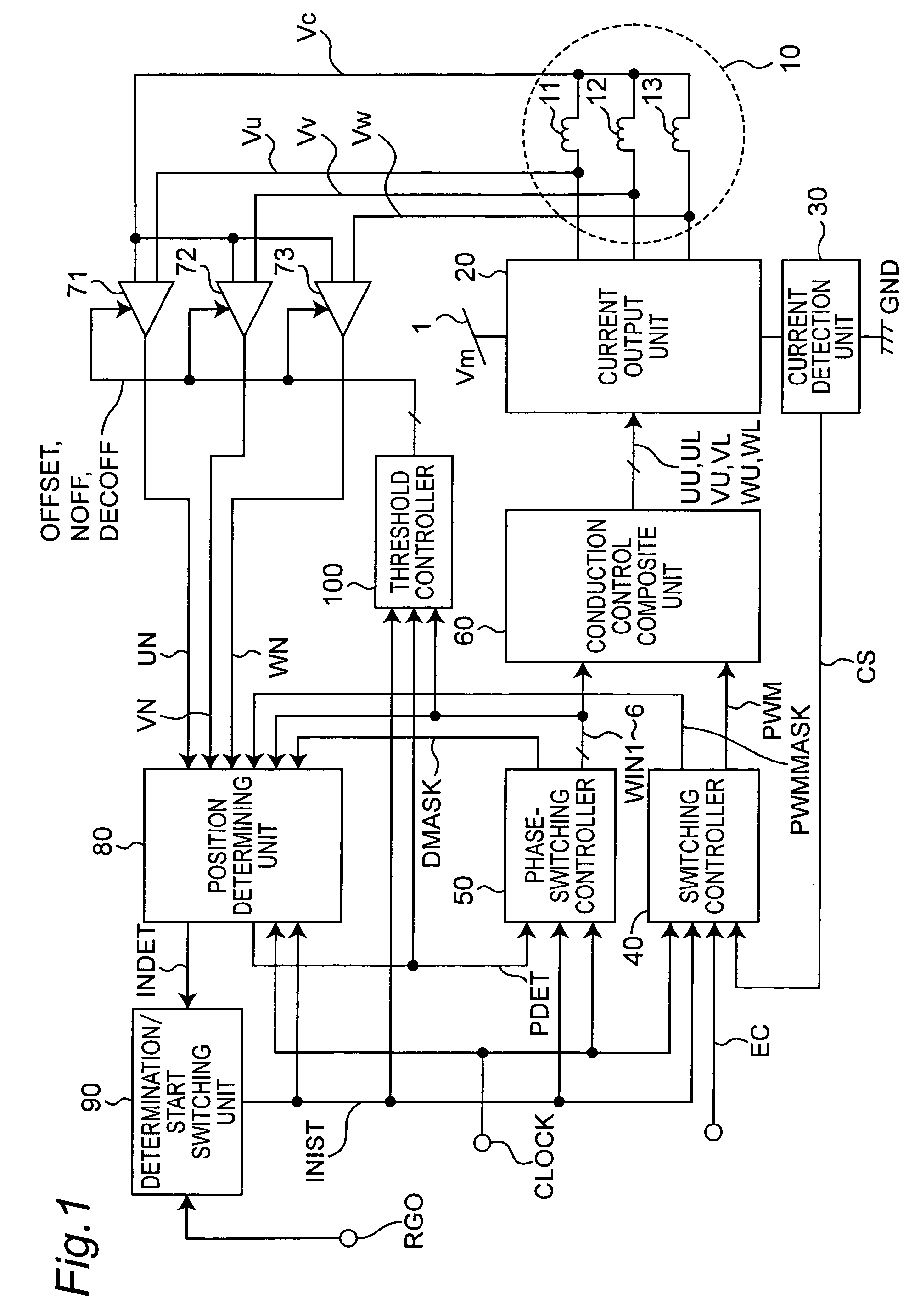
[0046]FIG. 1 shows a structure of a sensor-less motor driving apparatus in accordance with Embodiment 1 of the present invention. A motor 10 to be controlled by the motor driving apparatus of the present embodiment includes a rotor having a magnetic field section formed by a permanent magnet and a stator having Y-connection of a U-phase winding 11, a V-phase winding 12 and a W-phase winding 13.

[0047]The sensor-less motor driving apparatus is provided with a current output unit 20, a current detection unit 30, a switching controller 40, a phase-switching controller 50, a conduction control composite unit 60, comparators 71, 72 and 73, a position determining unit 80, a determination / start switching unit 90 and a threshold controller 100.

[0048]Signals to be transmitted and received in the motor driving apparatus of the present embodiment are described below.[0049]CLOCK: A clock signal (duty ratio=50% in the present embodiment).[0050]DMASK: A mask signal for masking a ringing period of ...

embodiment 2

[0117]In Embodiment 1, as shown in FIG. 18A, a period in which all the phases are set to high impedance during on-period of the signals WIN1 to 6 of the respective phases is provided. This arrangement is made so as to once set, to zero, a current in a stator winding generated on application of a current, consequently to achieve an accurate detection in the next detecting operation. However, as shown in FIG. 18A, the residual current in the winding becomes zero in a comparatively early stage during the high impedance period of the all phases. After the residual current becomes zero, it is not necessary to set all the phases to high impedance state, and as the high impedance period of all the phases becomes shorter, it becomes possible to shorten the processing time as a whole. Therefore, the present embodiment will discuss an arrangement for shortening the time required for determining the position by shortening the high impedance period of all phases in comparison with the arrangeme...


PUM


Abstract

A motor driving apparatus includes a comparator, a threshold controller, a position determining unit, a phase-switching controller, and a current output unit. While the rotor is stopped, the phase-switching controller supplies a predetermined phase of winding with a current pulse having a predetermined pulse width so as not to cause the rotor to react and operate, in order to determine the initial position of the rotor. The position determining unit determines an initial position of the rotor based on the result of comparison between the induced voltage generated in a non-conduction phase by the current pulse and the threshold. The phase-switching controller performs energization or commutation according to the determined initial position of the rotor to start up the motor.

Description

BACKGROUND OF THE INVENTION[0001]1. Field of the Invention[0002]The present invention relates to a motor driving technique, and more particularly to a driving apparatus and a method that drive a motor in a position sensor-less system to detect a rotor position based on a zero-cross point of a back electromotive force generated in a non-conduction phase of windings.[0003]2. Related Art[0004]In recent years, a brush-less motor has been generally used as a spindle motor for a hard disk, an optical disk and the like, or as a fan motor and a compressor-driving motor for an air conditioner. In general, the brush-less motor is driven in PWM control by an inverter so as to provide a variable speed controlling operation in a wide range and also to achieve low power consumption.[0005]Inside the brush-less motor having three-phase windings, in general, position sensors such as hole elements are placed at every electrical angle of 120 degrees so as to detect the position of a magnetic pole of a...

Claims


Application Information

Patent Timeline
Patent Type & Authority Patents(United States)
IPC IPC(8): H02P6/18H02P6/06H02P6/08H02P6/17H02P6/182H02P6/21
CPCH02P6/182H02P6/205H02P6/21
Inventor KUROSHIMA, SHINICHIIGARASHI, YOSHIAKIMORI, HIDEAKI
Owner COLLABO INNOVATIONS INC
Why Eureka
Try Eureka