LAN magnetic interface circuit

a magnetic interface circuit and circuit technology, applied in the direction of fixed transformers or mutual inductances, line-transmission details, inductances, etc., can solve the problems of high impedance to common-mode signals and noise, potential to cause emi, emi (electromagnetic interference), etc., to improve emi performance and cost.

Active Publication Date: 2006-10-17
BEL FUSE
View PDF5 Cites 42 Cited by
  • Summary
  • Abstract
  • Description
  • Claims
  • Application Information

AI Technical Summary

Benefits of technology

[0022]It is an object of the present invention to provide a new magnetic circuit topology configuration, which provides greatly improved EMI performance compared to the standard topologies without compromising signal integrity or adding cost.

Problems solved by technology

Simply stated, the CMC allows data signals (differential-mode) to pass through it unimpeded, but presents a high impedance to common-mode signals and noise.
Such common-mode noise is the major cause of EMI (electromagnetic interference).
Such noise has the potential to cause EMI.
However, these circuit topologies were developed years ago when CPU, data buses, and clock speeds were relatively low and EMI was easier to control.
Modern day networking equipment, on the other hand, is far more difficult to achieve EMI compliance for many reasons.
1) Advances in technology are yielding extremely complex integrated circuits and system designs with very high circuit densities, very high clock and data bus speeds, and much lower supply voltages.
This, combined with the enormous number interconnecting traces and via's on the system PCB (printed circuit board), has the undesired consequence of increased noise and EMI generation.
This is particularly true for systems with inferior PCB layouts, meaning that the PCB was not designed in accordance with established PCB design rules that must be instituted in order to minimize EMI caused by the PCB layout itself.
Consequently, noise present on signal and power rail is conducted directly into ICM and onto the circuit-side winding of the isolation transformer.
This noise will pass through the parasitic interwinding capacitance of the isolation transformer, and / or through other parasitic paths, to the line-side where it will be conducted onto a data cable plugged into the port and / or radiate out of the RJ45 port, causing system EMI problems.
There are several inherent disadvantages associated with this basic configuration that commonly leads to system EMI problems.
Pulsed currents, which are drawn from V+ by operation of the switches A and B to drive the transformers, generate noise on the V+ power rail.
This is substantial in multi-port systems, wherein many channels are switching on and off at the same time, placing high transient current loads on the V+ power rail.
These transient currents can generate voltage spikes, high frequency ringing, droop, and overshoot, which will corrupt the V+ power rail.
This noise will then couple to the line-side of the transformer through the transformer's inter-winding capacitance, and through other parasitic paths, where it will be conducted onto a data cable plugged into the port and / or radiate out of the RJ45 port, causing system EMI problems.
Again, noise present on these signal lines will couple through inter-winding capacitance and other parasitic paths to the line-side of the transformer where it will be conducted onto a data cable plugged into the port and / or radiate out of the RJ45 port, causing system EMI problems.
3) 100 Mbps and Gigabit Ethernet transceiver ICs utilize a 125 MHZ clock and incorporate multiple phased locked loops (PLL) running at 125 MHZ. Consequently, and in addition to digital noise from other sources, there will be a strong 125 MHZ presence within the circuit and on the signal and power planes, especially in multi-port systems which have several Ethernet transceiver ICs driving up to 48 ports. This 125 MHZ component, and often to a much greater extent, its harmonics (250, 375, 500, 625, 750, 875 and 1000 MHZ), will pass to the secondary-side of the transformer and are among the worst offending frequencies that cause EMI problems in networking systems
However, the extent of refinement needed to reduce EMI to acceptable levels will significantly increase labor and material costs and can often cause degradation of other electrical performance parameters, which can compromise signal integrity.
Additionally, such “improved” designs will not always provide improved EMI performance in different applications or systems platforms.

Method used


Image

  • LAN magnetic interface circuit
  • LAN magnetic interface circuit
  • LAN magnetic interface circuit

Examples


Embodiment Construction

[0032]The invention will be described in connection with its applicability to EMI suppression in magnetic interface Ethernet applications; however, the invention is not so limited and is equally applicable to other networking applications. Components having the same or similar function are designated with the same reference numerals.

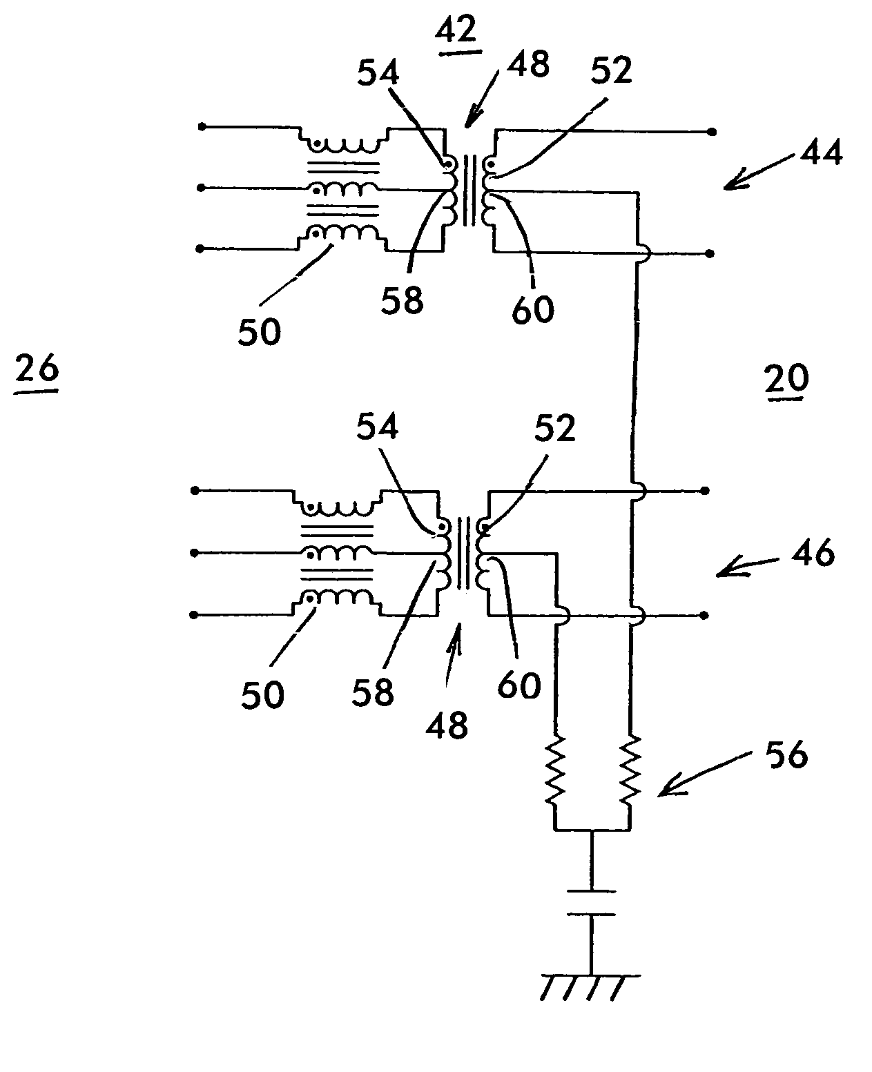
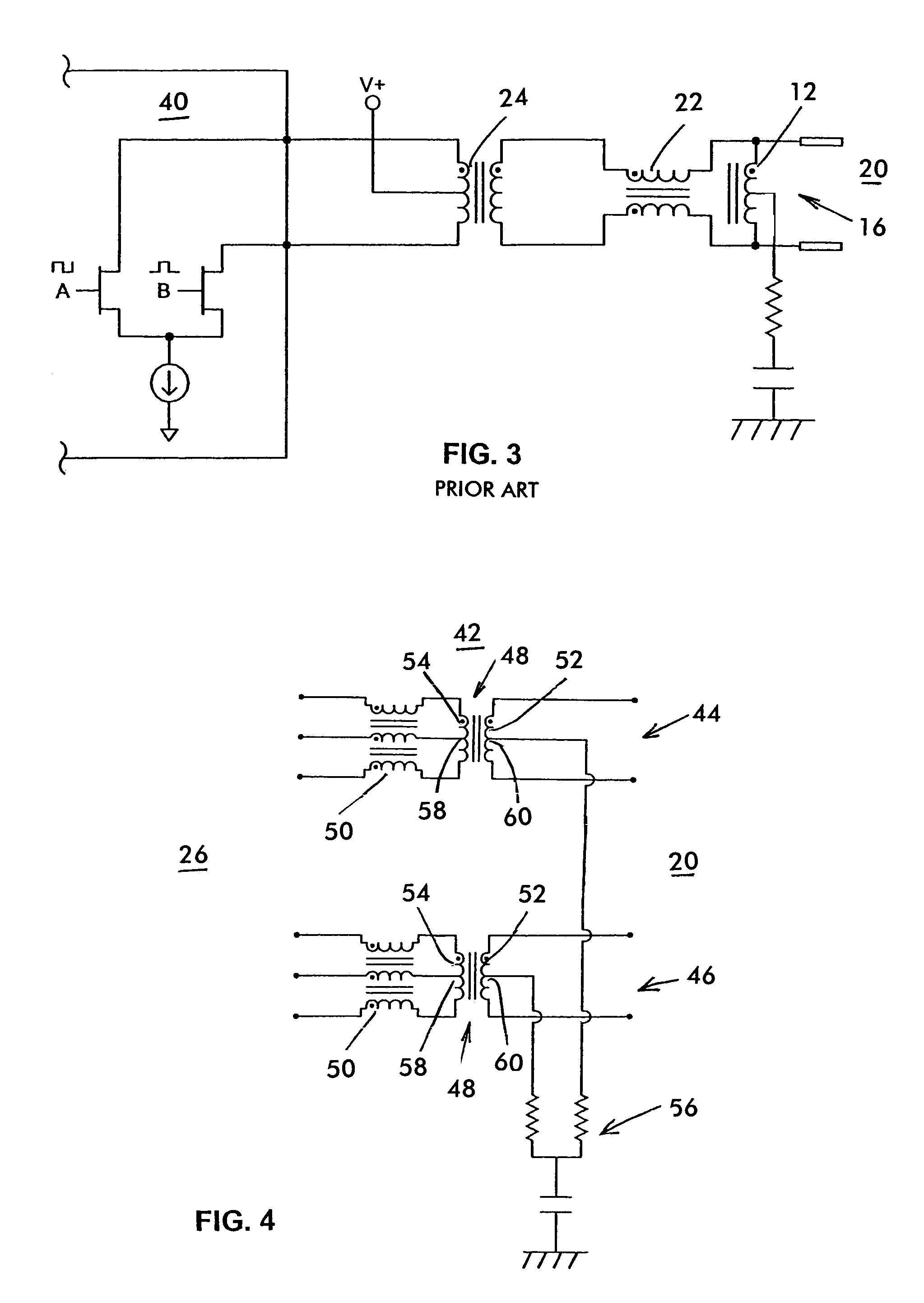
[0033]FIG. 4 shows a LAN magnetic interface circuit topology 42 in accordance with certain features of the present invention. The circuit 42 includes two channels: a transmit channel 44 and a receive channel 46. Each channel is identical and includes an isolation transformer 48 and a 3-wire CMC 50 with one of the windings of the isolation transformer 48 connected to the line side 20 of the port and the 3-wire CMC 50 connected between the other winding of the isolation transformer 48 and the circuit side 26 of the channel. A termination network 56 is connected to each of the channels.

[0034]The circuit 42 is hereinafter referred to as the “3-Wire CMC embod...


PUM

PropertyMeasurementUnit
magneticaaaaaaaaaa
DC voltageaaaaaaaaaa
electromagnetic interferenceaaaaaaaaaa

Abstract

A magnetic interface circuit for a LAN, such as an Ethernet network, includes a transformer having a first winding connected to the line side of the LAN and a second winding connected to the circuit side of the LAN. Each of the first and second windings has two output ports and one of the windings has a center tap port A 3-wire common mode choke having a center winding and two outer windings, the center winding of a 3-wire common mode choke is connected to the center tap of the one winding and the outer windings of the 3-wire common mode choke are respectively connected to the output ports of the one winding.

Description

CROSS-REFERENCE TO RELATED APPLICATIONS[0001]This application is based on and claims the benefit of U.S. Provisional Application No. 60 / 472,448, filed May 21, 2003, and entitled “IMPROVED LAN MAGNETIC INTERFACE CIRCUIT,” the entire disclosure of which is incorporated by reference herein.BACKGROUND OF THE INVENTION[0002]The present invention relates generally to LAN (local area network) magnetic interface circuits and, more particularly, to LAN magnetic interface circuits having improved EMI (electromagnetic interference) performance.[0003]One of the basic requirements for a LAN magnetic interface circuit is to provide electrical isolation. This is achieved by the use of an isolation transformer. The isolation transformer electromagnetically couples signals (data) from the primary-side (circuit side) to the secondary-side (line side). Hence, the primary and secondary windings of the transformer are electrically isolated from each other. The transformer is designed to meet the Hi-Pot ...

Claims


Application Information

Patent Timeline
Patent Type & Authority Patents(United States)
IPC IPC(8): H03H7/00H01F17/00H01F17/06H01F19/08H01F38/02H03H7/38H04L29/06
CPCH01F17/00H01F19/08H01F17/06H01F38/023H01F2019/085H01F2038/143H03H7/38
Inventor CHEN, JOHNCONTRERAS, STEVE
Owner BEL FUSE
Why Eureka
Try Eureka