Field emitter X-ray source and system and method thereof

a field emitter and emitter array technology, applied in the direction of x-ray tube cathode assembly x-ray tube gas control, etc., can solve the problem of contaminants on the field emitter array, and achieve the effect of reducing the deposition of contaminants

Active Publication Date: 2006-10-17
GENERAL ELECTRIC CO
View PDF7 Cites 11 Cited by
  • Summary
  • Abstract
  • Description
  • Claims
  • Application Information

AI Technical Summary

Benefits of technology

[0006]Briefly, in accordance with one embodiment, the present technique provides an X-ray source. The X-ray source includes a field emitter array having a plurality of field emitter elements disposed in a vacuum chamber and configured to emit electrons in the vacuum chamber towards an anode assembly. The X-ray source also includes an anode disposed in the vacuum chamber for receiving the electrons emitted by the field emitter array, and configured to thereby generate X-ray radiation. The X-ray source further includes a source of cleaning gas coupled to the vacuum chamber, wherein the source of cleaning gas is configured to provide cleaning gas to the vacuum chamber towards the field emitter array to reduce deposition of contaminants on or to clean contaminates from the field emitter array.

Problems solved by technology

The method also includes receiving the emitted electrons on an anode to produce X-ray radiation that is emitted from the vacuum chamber, operation of the field emitter array and anode resulting in deposition of contaminants on the field emitter array.

Method used


Image

  • Field emitter X-ray source and system and method thereof
  • Field emitter X-ray source and system and method thereof
  • Field emitter X-ray source and system and method thereof

Examples


Embodiment Construction

[0016]The present technique is generally directed towards an X-ray source, which may be used for medical and non-medical applications, and likewise for imaging and non-imaging applications. Such applications may include, without limitation, patient evaluation, and passenger and / or baggage screening, and generally to provide useful two-dimensional and three-dimensional data and context. To facilitate explanation of the present techniques, however, medical implementations will be generally discussed herein, though it is to be understood that non-medical implementations are also within the scope of the present techniques.

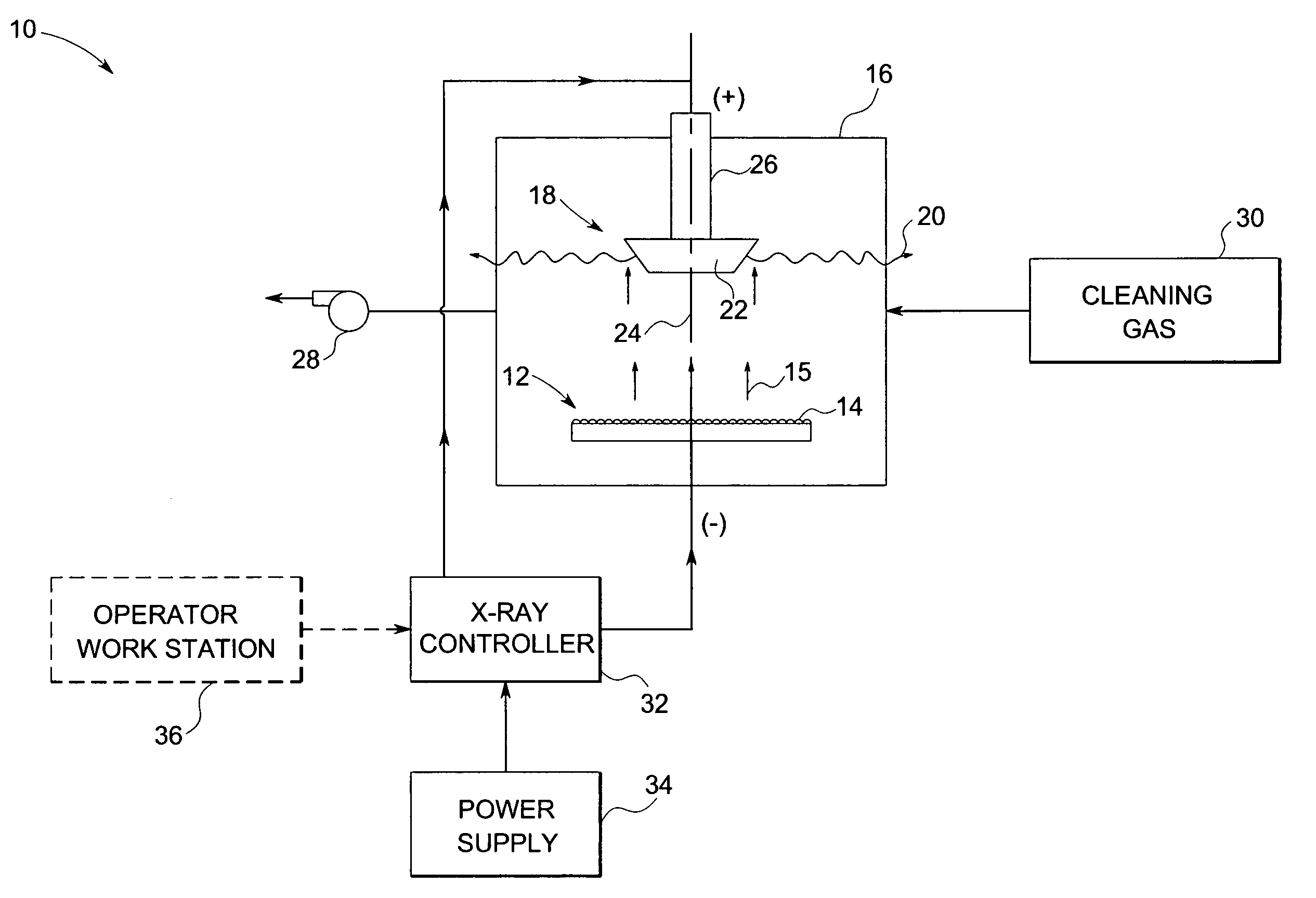
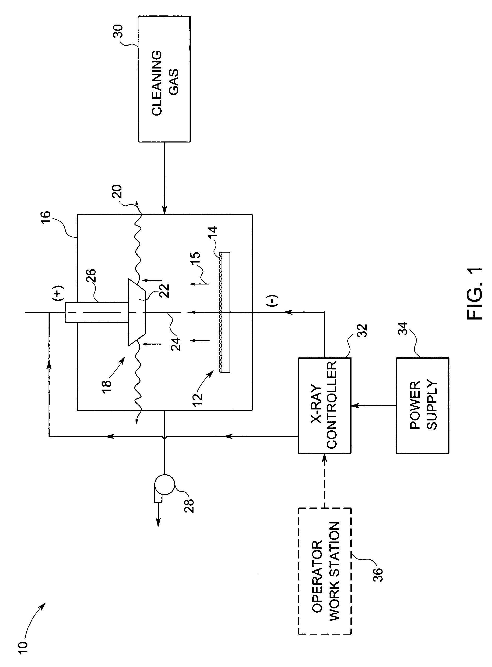
[0017]Turning now to the drawings, and referring first to FIG. 1, an exemplary embodiment of an improved field emitter X-ray source system 10 for use in accordance with the present technique is illustrated diagrammatically. The field emitter X-ray source system 10 includes a field emitter array 12 having a number of field emitter elements 14. The X-ray source system 10...


PUM


Abstract

In accordance with one embodiment, the present technique provides an X-ray source. The X-ray source includes a field emitter array having a plurality of field emitter elements disposed in a vacuum chamber and configured to emit electrons in the vacuum chamber towards an anode assembly. The X-ray source also includes an anode disposed in the vacuum chamber for receiving the electrons emitted by the field emitter array and configured to thereby generate X-ray radiation. The X-ray source further includes a source of cleaning gas coupled to the vacuum chamber, wherein the source of cleaning gas is configured to provide the cleaning gas to the vacuum chamber towards the field emitter array to reduce deposition of contaminants on or to clean contaminates from the field emitter array.

Description

BACKGROUND[0001]The present invention relates generally to generating X-rays, and specifically to an improved method and system for generating X-rays using a field emitter X-ray source.[0002]X-ray systems are generally utilized in various applications, such as for imaging in the medical and non-medical fields. For example, X-ray systems, such as radiographic systems, computed tomography (CT) systems, and tomosynthesis systems, are used to create images or views of tissues of a patient based on the attenuation of X-ray beams passing through the patient. X-ray systems and sources may also be utilized to in non-medical applications, such as detecting minute flaws in equipment or structures, and scanning baggage, crystallography, to mention only a few.[0003]Typically, a X-ray system includes an X-ray source that generates X-ray beams that are directed towards a detector or film. Conventional X-ray tubes generate a beam of X-rays by bombarding a rotating anode with a stream of electrons ...

Claims


Application Information

Patent Timeline
Patent Type & Authority Patents(United States)
IPC IPC(8): H01J35/32H01J35/06H01J35/08
CPCH01J35/065H01J35/20H01J2235/062H01J2235/068H01J2235/20
Inventor WILSON, COLIN RICHARD
Owner GENERAL ELECTRIC CO
Why Eureka
Try Eureka