Frequency converter and methods of use thereof

a frequency converter and converter technology, applied in the field of digital frequency converters, can solve the problems of difficult to understand and predict the loop behavior of the loop, the practical implementation of analog pll based frequency converters is often limited, and the difficulty of real-time use of analog plls for accurate frequency conversion

Active Publication Date: 2006-10-17
TAMIRAS PER PTE LTD LLC
View PDF13 Cites 24 Cited by
  • Summary
  • Abstract
  • Description
  • Claims
  • Application Information

AI Technical Summary

Problems solved by technology

Capacitive elements in these analog PLL components introduce significant loop time constants and phase jitter that result in loop behavior that is difficult to understand, and predict, especially when the source frequency SCLK rapidly changes.
Moreover, practical implementations of analog PLL based frequency converters are often limited to a small compare period (i.e., a small values of F and S) because a large compare period requires a larger capacitor in filter 110, which is impossible in many applications.
For at least these reasons, analog PLLs are very difficult to practically use for accurate frequency conversion, especially when the source frequency SCLK is not a constant value.
If the SCLK period varies over a wide range (i.e., has high jitter), then it may be difficult (or impossible) to design the output module to reduce the jitter effectively.
In some cases, however, it is impossible to have large common denominator.
However, in many CRT / LCD monitor applications a long response time is not acceptable.
As can be appreciated, phase detector 454 performs both logical and calculation operations, and is, therefor, generally difficult to design.

Method used


Image

  • Frequency converter and methods of use thereof
  • Frequency converter and methods of use thereof
  • Frequency converter and methods of use thereof

Examples


Embodiment Construction

[0045]The present invention will now be described with reference to an embodiment thereof as illustrated in accompanying drawings. In the following description, specific details are set forth in order to provide a better understanding of present invention. It will be apparent, however, to one skilled in the art, that the present invention may be practiced without some or all of these specific details. In other instances, well-known steps and / or system components have not been described in detail in order to not unnecessarily obscure the present invention.

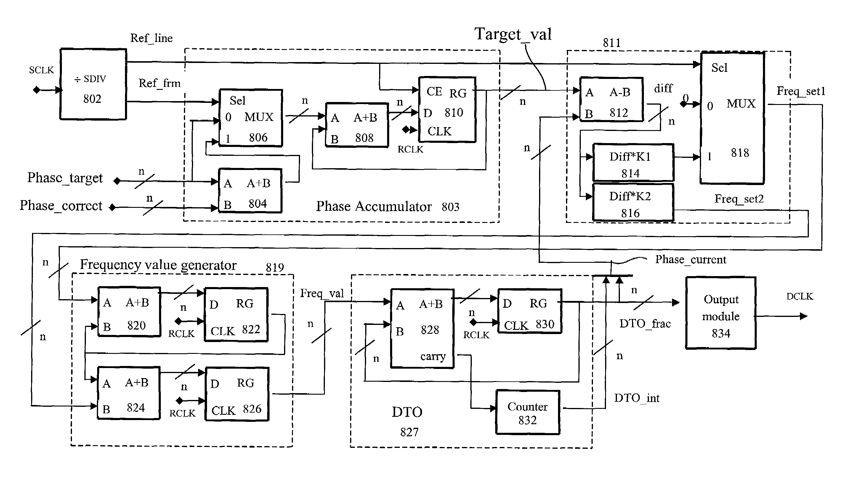
[0046]In view of the foregoing, and to achieve other objects of the invention, an all-digital frequency converter is provided that has fast response time and relatively simple design. The general direct digital synthesis (DDS) servo system according to an embodiment of the present invention is illustrated by way of the block diagram in FIG. 5. The DDS servo frequency conversion system shown in the figure is a frequency converter tha...


PUM


Abstract

An all-digital frequency conversion apparatus is provided that achieves frequency conversion using a simple phase detector and integer and fractional phase feedback information from a digital oscillator output. In an embodiment, a target phase accumulator unit generates a target phase signal to the phase detector unit. The target phase accumulator unit receives inputs from a reference signal input, and a target phase input value. The digital phase detector unit receives the reference signal, a current phase feedback input signal, and the target phase input signal. The phase detector unit outputs a frequency setting signal to a frequency value generator unit. The detector output is based on the difference between the current phase and the target phase. A frequency value generator unit is configured to output a frequency value signal to a digital oscillator unit that generates a corresponding digital output signal that is directly fed back to the current phase feedback input of the phase detector unit. A method, computing system, and software product that implement the present invention are also provided.

Description

FIELD OF THE INVENTION[0001]The present invention relates generally to frequency converters. More particularly, the invention relates to a digital frequency converter that precisely adjusts a reference frequency.BACKGROUND OF THE INVENTION[0002]In many types of electrical systems it is desirable to generate clock signals with various frequency and phase relationships synthesized from certain reference signals. A common way to synthesize derivatives of a reference signal is based upon the analog phase locked loop (PLL) frequency converter. Accordingly, FIG. 1 shows a traditional analog PLL 100 that takes a digital source frequency SCLK as an input to a source divider 104 that divides SCLK by an integer value S to create reference frequency fREF. A negative feedback PLL control loop 105 is formed by a phase detector 106, a charge pump 108, a low pass loop filter 110, a voltage controlled oscillator (VCO) 112, and a feedback divider 114. Phase detector 106 performs a phase difference o...

Claims


Application Information

Patent Timeline
Patent Type & Authority Patents(United States)
IPC IPC(8): G06F7/52H03K21/00H03L7/06G06F1/08H03L7/091H03L7/099
CPCG06F1/08H03L7/091H03L7/0994H03L2207/50H03K5/13H03L7/08
Inventor GRUSHIN, STANISLAV
Owner TAMIRAS PER PTE LTD LLC
Why Eureka
Try Eureka