
3-D construction modules

a technology of prefabricated construction modules and construction modules, applied in the field of construction, can solve the problems of high labor intensity, complex and costly implementation of known design for reinforcement support, and the associated heat can have a negative impact on the structural stability of a concrete wall

Inactive Publication Date: 2006-10-24
BRAVINSKI LEONID G
View PDF39 Cites 59 Cited by
  • Summary
  • Abstract
  • Description
  • Claims
  • Application Information

AI Technical Summary

Benefits of technology

[0010]In one aspect of the present invention, there is provided a 3D construction module comprising: a) a vertically upstanding panel oriented generally longitudinally; b) first and second mesh layers oriented generally transversely and longitudinally, each of said first and second mesh layers comprising at least one rod member mounted to said panel, said first and second mesh layers being vertically spaced from each other; said at least one rod member of said first mesh layer configured to co-operate with said at least one rod member of said second mesh layer to form a first horizontally projected retention cell to restrict translation of a bar held in said retention cell between said first and second mesh layers; whereby said first retention cell forms a generally vertically oriented opening for receiving a vertical reinforcement member and said retention cell restricts translation movement longitudinally and transversely of a vertical reinforcement member held in said retention cell.
[0018]In another aspect of the present invention, there is provided a construction combination comprising: a) a mesh comprising a first longitudinal rod member and a plurality of transverse rod members connected to said longitudinal rod member; b) a stopper member for each of said plurality of transverse rod members, each stopper member having a leg portion and a first flange portion, and an axial passageway through said leg portion and said first flange portion, said passageway for freely receiving a rod member there through, said stopper member movable axially on said rod member, said first flange portion adapted to be moved into abutment an inner surface of a panel, said leg portion adapted to be moved into abutment with said longitudinal member, whereby said flange member can co-operate with connector connecting said panel with a transverse rod to properly position said connector and can co-operate with said panel to properly position said inner surface of said panel relative to said longitudinal member.
[0020]In another aspect of the present invention, there is provided a 3D construction module comprising: first and second mesh layers oriented generally transversely and longitudinally, each of said first and second mesh layers comprising a plurality of transversely oriented, and spaced transverse rod members, each of said transverse rod members having an end adapted for mounting to a panel, said plurality of transverse rod members being interconnected to first and second longitudinally oriented and spaced longitudinal rod members, said first and second mesh layers being vertically spaced from each other; at least one of said transverse rod members and one of said first and second longitudinal rod members of said first mesh layer configured to co-operate with at least one of said transverse rod members and one of said first and second longitudinal rod members of said second mesh layer to form a first horizontally projected retention cell to restrict translation of a bar held in said retention cell between said first and second mesh layers; whereby said first retention cell forms a generally vertically oriented opening for receiving a vertical reinforcement member and said retention cells restrict translation movement longitudinally and transversely of a vertical reinforcement member held in said retention cell.
[0023]In another aspect of the present invention, there is provided a method of fabricating a 3D construction module comprising: a) providing a vertically upstanding panel oriented generally longitudinally; b) securing first and second mesh layers to said panel such that they are oriented generally transversely and longitudinally, each of said first and second mesh layers comprising at least one rod member mounted to said panel, and said first and second mesh layers being arranged in vertically spaced relation to each other; c) arranging said at least one rod member of said first mesh layer and said at least one rod member of said second mesh layer to form a first horizontally projected retention cell to restrict translation of a bar held in said retention cell between said first and second mesh layers; whereby said first retention cell forms a generally vertically oriented opening for receiving a vertical reinforcement member and said retention cell restricts translation movement longitudinally and transversely of a vertical reinforcement member held in said retention cell.

Problems solved by technology

To date, most of the known designs for reinforcement support are complex and costly to implement.
Also, it should be noted, that there is a high consumption of labor when connecting 3D prefabricated construction modules and reinforcement member (ie. rebar) extensions from concrete structures beneath the modules, such as foundations, in order to provide continuous reinforcement.
It is well known that fire and its associated heat can have a negative impact on structural stability of a concrete wall, and on the ability of the wall or other element to contain the fire.
There is a tendency of such panels to melt when subjected to heat on one side of a wall caused by a fire in the vicinity of the wall.
This can cause the fire to move along a path directly toward the wall and can create an intense fire situation right at or in the immediate vicinity of the wall.
This of course has an extremely detrimental effect, both on the structural stability of the wall, as well as its ability to contain the fire.

Method used


Image

  • 3-D construction modules
  • 3-D construction modules
  • 3-D construction modules

Examples


Embodiment Construction

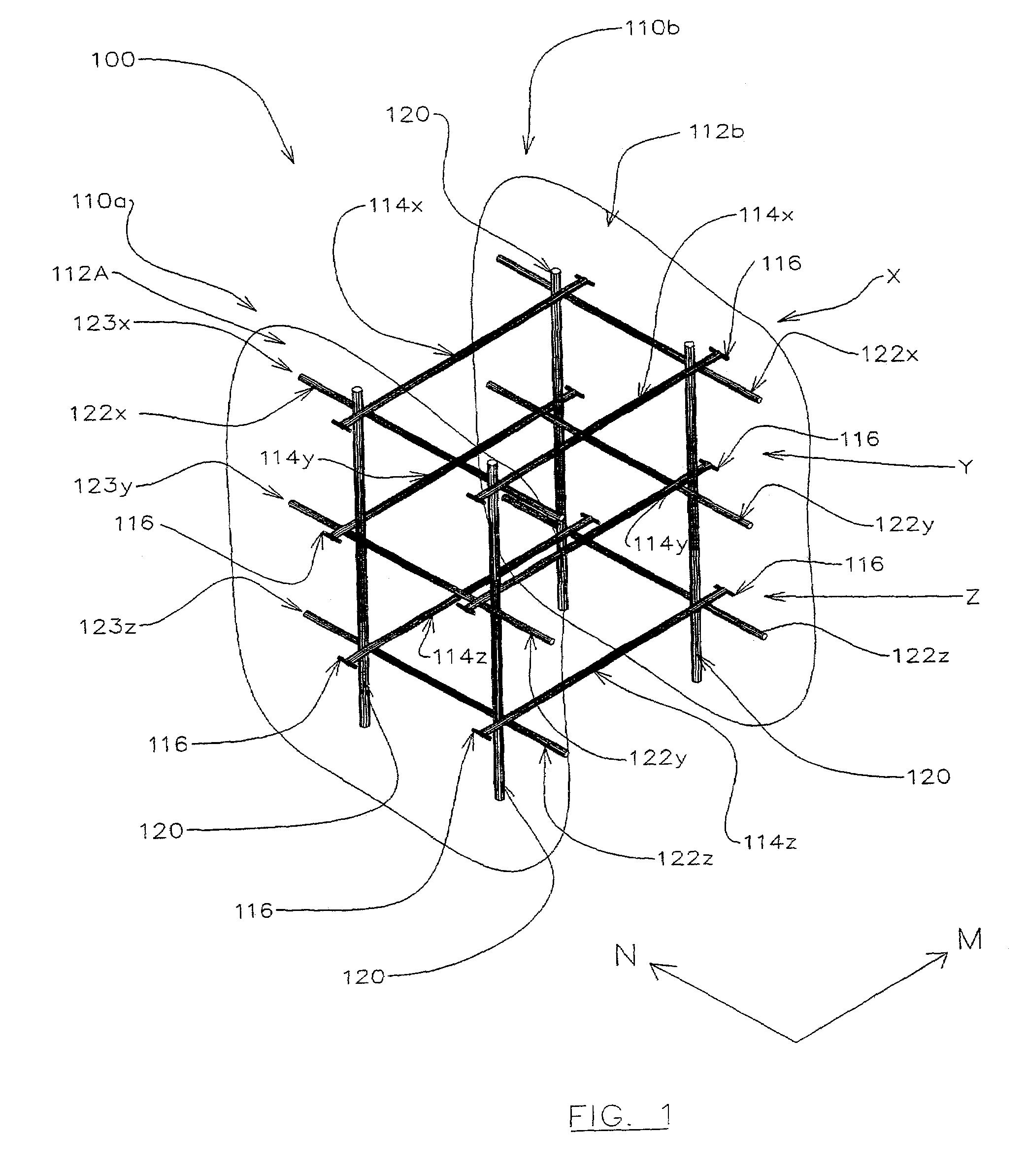
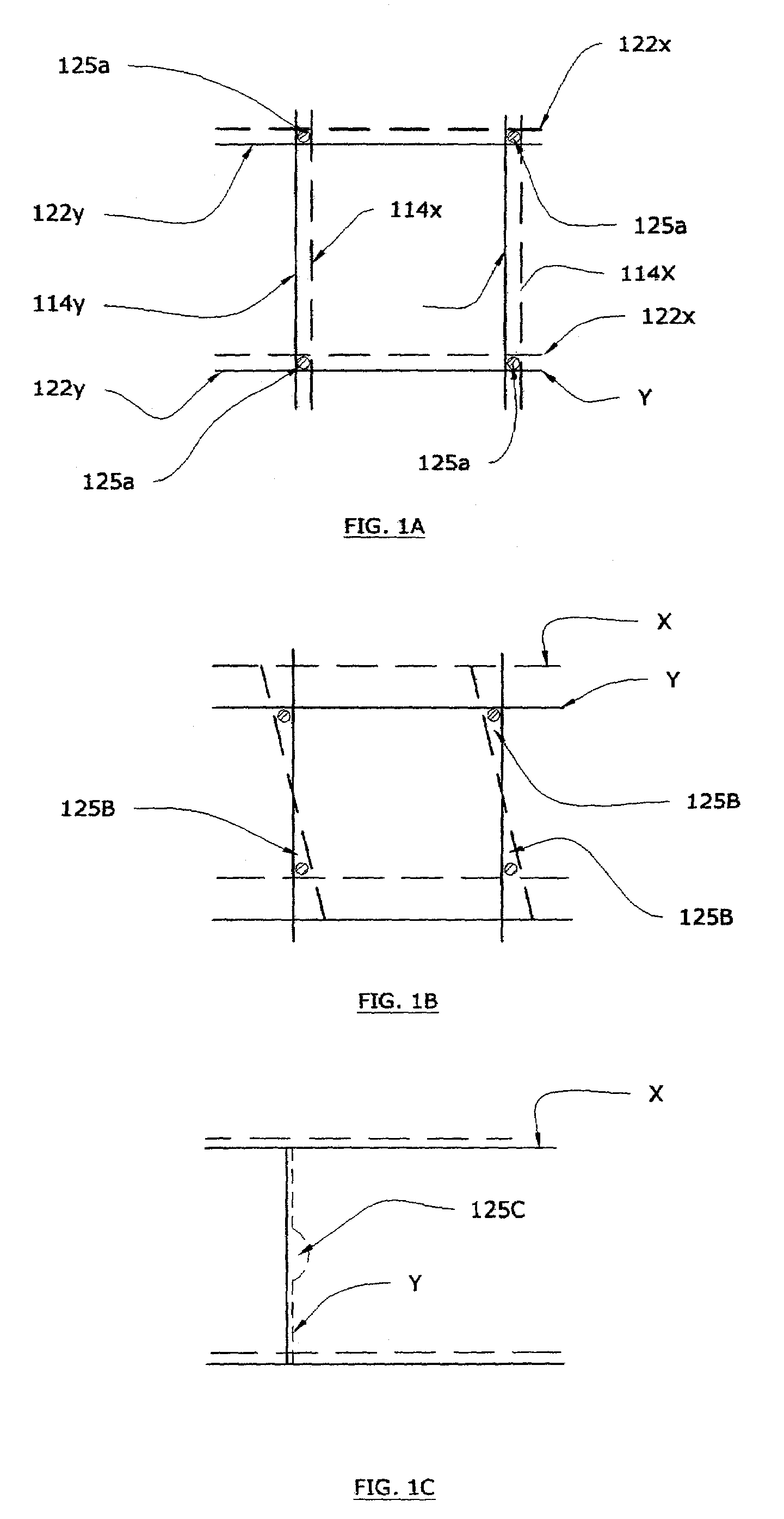
[0117]With reference to FIG. 1, a schematic representation of part of a 3D construction module 100 is shown. Module 100 is preferably pre-fabricated prior to delivery to a construction site or directly on the construction site prior to installation into the design position, and comprises a pair of panels 110a, 110b (only portions 112a and 112b being shown in FIG. 1). Panels 110a, 110b held in spaced apart relation by means of transverse elements in the form of pairs of transverse rod members 114x, 114y and 114z each pair positioned in one of three vertical layers x, y and z.

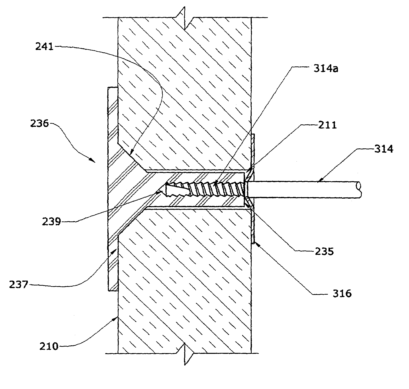
[0118]The transverse rods each have stopper elements 116 mounted perpendicularly to the longitudinal axis of the transverse rods. The transverse rods ends are fixed to the panels 110a and 110b (although FIG. 1 does not show the attachment mechanism). The end of the transverse rods (referenced collectively as 114) can be attached to the panels 110 as described below, or in other conventional ways.

[0119]Stoppers 16...


PUM


Abstract

A 3D construction module comprising at least one vertically upstanding panel with first and second mesh layers oriented generally transversely and longitudinally. The first and second mesh layers have at least one rod member mounted to said panel and are vertically spaced from each other. The rod members form a first horizontally projected retention cell to restrict translation of a bar held in said retention cell between said first and second mesh layers. A third mesh can also be provided to form a second retention cell between said second and third mesh layers. The first and second retention cells restrict translation movement longitudinally and transversely of a vertical reinforcement member held in said first and second retention cells, and restrict rotation of the vertical reinforcement member about both a longitudinal axis and a transverse axis of the said 3D construction module. Horizontal reinforcement meshes are features of the invention. Other features of the invention include a trough for holding melted panel material, connectors for connecting rods to panels and associated stopper members. Also included are bracers for joining connectors and other devices related to panel connections.

Description

FIELD OF THE INVENTION[0001]The present invention relates to the field of construction, and in particular to the construction of poured-in-place reinforced concrete walls and other structural elements, and to their construction with 3D form modules. These modules can be prefabricated both prior to transportation to a construction site and directly on the construction site prior to installation into the design position.BACKGROUND[0002]At the present time, the most advanced method of making reinforced concrete walls and similar structural elements, uses 3D prefabricated construction modules comprising parallel panels spaced from each other. The modules also include transverse elements in the form of grids or meshes preferably horizontally oriented and fixed to the panels, and include connectors joining transverse elements and panels. The transverse elements usually have stopping details, which usually serve as support for panels. These 3D prefabricated construction modules can be made...

Claims


Application Information

Patent Timeline
Patent Type & Authority Patents(United States)
IPC IPC(8): E04B2/00E02D27/02E04B1/16E04B1/61E04B2/56E04B2/86E04C5/16
CPCE02D27/02E04B1/161E04C5/168E04C5/203E04B1/6145E04B2/8647E04B2002/565
Inventor BRAVINSKI, LEONID G.
Owner BRAVINSKI LEONID G
Learn More