
Horizontal cutter of double-bodied bottles attached to each other at the neck

a cutter and bottle technology, applied in the direction of sawing equipment, hollow objects, turning equipment, etc., can solve the problems of reducing the output of the system, affecting productivity, and imprecise bottle rotation

Inactive Publication Date: 2006-10-24
CONSTRS MECANICAS MAER
View PDF22 Cites 7 Cited by
  • Summary
  • Abstract
  • Description
  • Claims
  • Application Information

AI Technical Summary

Benefits of technology

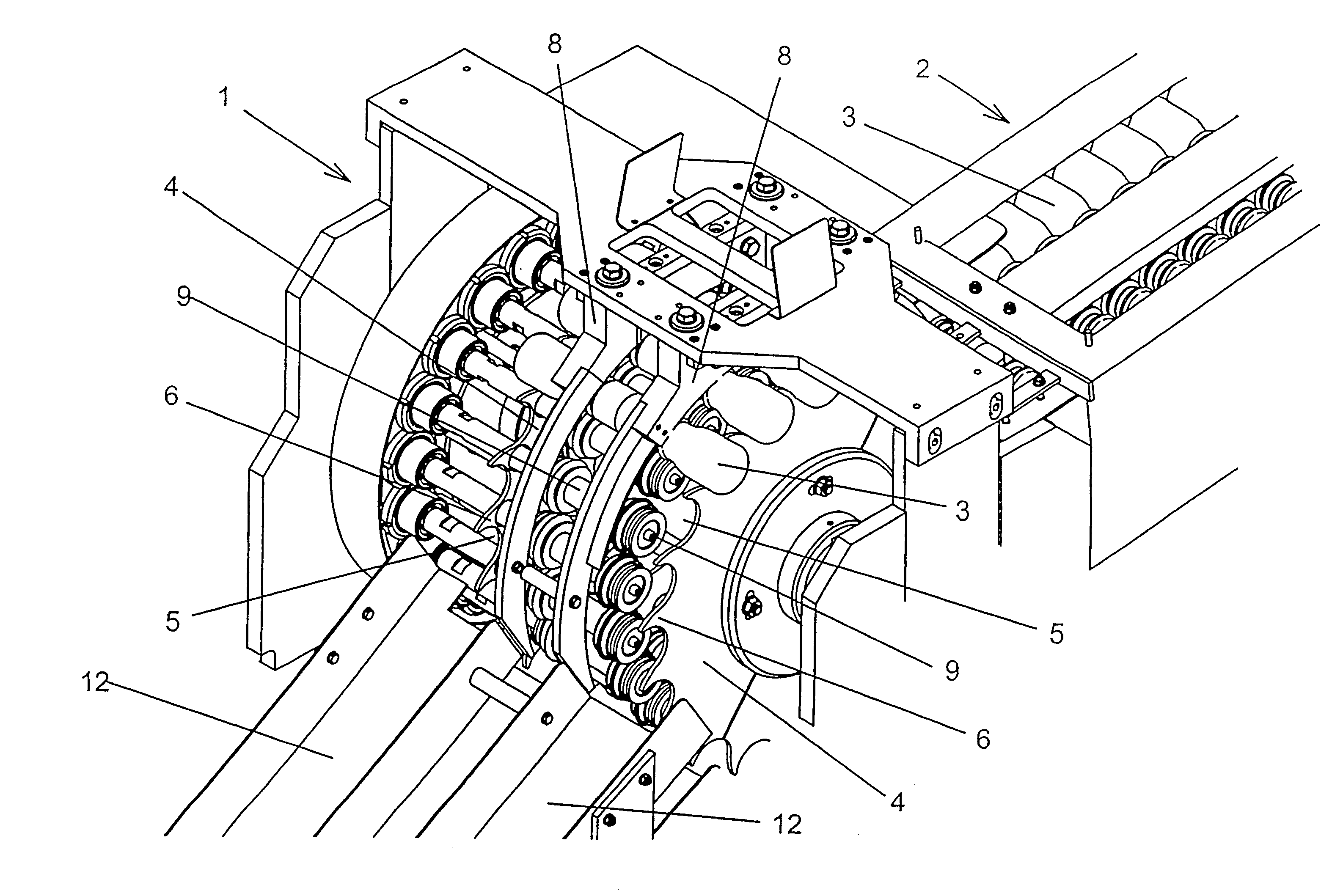
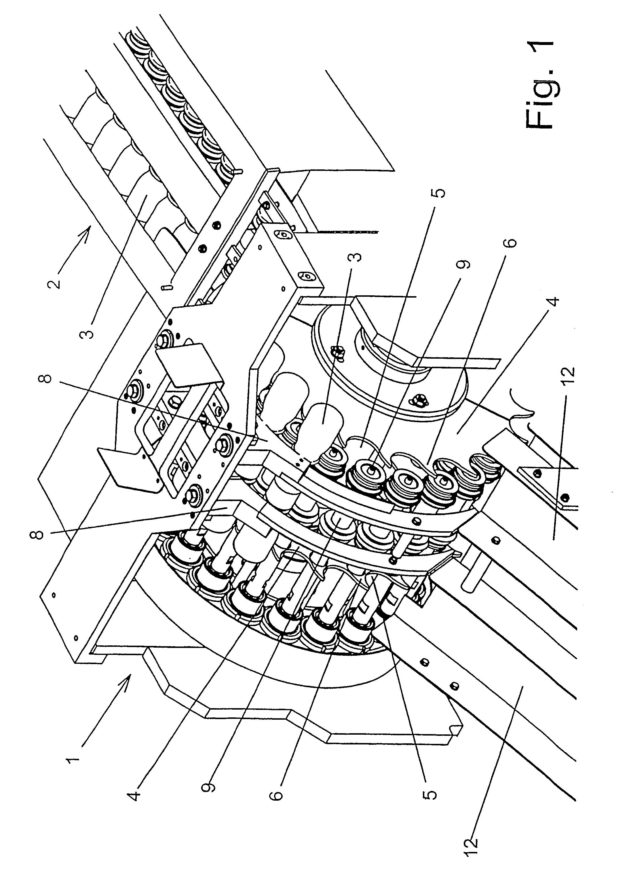
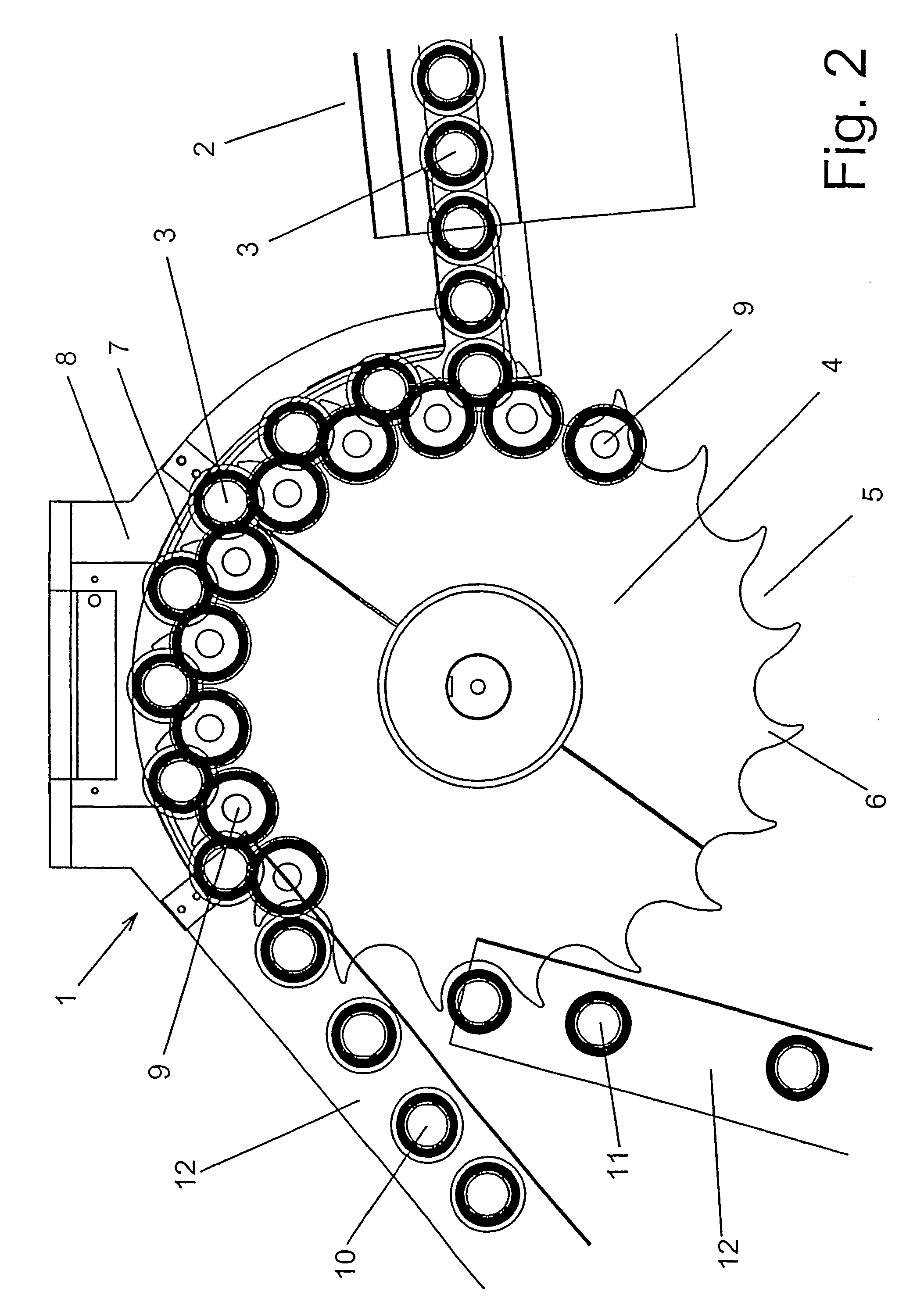
[0010]Thanks to these characteristics the bottles are made to move and to rotate about their own axes, this facilitating and speeding up the cutting operation.
[0020]Ejection and separation of the bottles is thus carried out quickly and effectively.

Problems solved by technology

These machines have the disadvantage that the rotation of the bottles becomes imprecise as their passing speed increases, since the rotation resistance caused by the cutting action of the blade disturbs the bottle's travel-path, in which the bottle has only one point of contact with the support tracks and another with the drive belt.
Furthermore, in order to implement the cutting of the bottles there has to be a certain space between them, since the bottle has to be able to rotate freely as the cut is being made, with no means other than the tracks and the drive belt in contact with it.
All these factors have an adverse effect on productivity, as the bottles often fall over or their path deviates at the cut is made.
Moreover, the limited cutting speed and the space that has to be left between one bottle and the next also reduces the output of the system.
This system further requires the cut to be made in a straight line, so that the machine takes up a considerable amount of space.
After the cut, however, and due to the melting of the material carried out by the blade, the bottles have a burr at the mouth that subsequently has to be removed, which involves increased costs and extra manufacturing time.

Method used


Image

  • Horizontal cutter of double-bodied bottles attached to each other at the neck
  • Horizontal cutter of double-bodied bottles attached to each other at the neck
  • Horizontal cutter of double-bodied bottles attached to each other at the neck

Examples


Embodiment Construction

[0008]The objective of this invention is to resolve the disadvantages of the devices known in the prior art, while further providing additional advantages that will become clear from the description that follows.

[0009]The machine for the cutting of double-bodied bottles attached to each other at the neck is of the type which comprises means for advancing the bottles and a bottle-neck cutting device, and is characterised in that said cutting device comprises means for rotating around their axis of symmetry a pair of parallel oriented rotary plates, a pair of arc shaped blades, which are oriented in parallel to the plane of said rotary plates and distanced in such a way that the double-bodied bottles can fit between the arc shaped blades and the rotary plates, a plurality of drive pulleys, which are parallel arranged to the axis of the rotating plates, and which in operation contact the neck of the bottles, whereby said rotary plates comprise a plurality of perimetral housings which a...


PUM

PropertyMeasurementUnit
symmetryaaaaaaaaaa
heightaaaaaaaaaa
perimeteraaaaaaaaaa

Abstract

A horizontal cutter of double-bodied bottles attached to each other at a neck which comprises means (2) for advancing the bottles (3) and a cutting device (1) of the neck of the bottles. The cutting device (1) comprises a pair of blades (7), a pair of rotating plates (4) for drawing the bottles (3) along and a plurality of drive pulleys (9) in contact with the bottles (3), in such a way that as the rotating plates (4) move so do the bottles, at the same time rotating about their axes and in contact with the blades. The horizontal cutter ensures fast and effective cutting of the bottles, while occupying little space.

Description

[0001]This invention relates to a horizontal cutter of double-bodied bottles attached to each other at the neck.BACKGROUND OF THE INVENTION[0002]Known in the art are horizontal cutting machines whose purpose is to provide two new single bottles by separating the two bodies of a double-bodied bottle manufactured previously by means of blowing, extrusion or other shaping methods.[0003]On such machines the bottles reach a cutting station in horizontal position by means of a conveyor belt with dividing segments and an end ramp. As the cut is made the bottles move along resting on a pair of tracks. A drive belt situated above the tracks makes contact with the upper part of the bottle, making it advance and rotate about its own axis. As the bottle advances a fixed blade located between the two tracks and gradually increasing their height performs the cut. Thanks to the bottle shifting and rotation movement the cut is made around the entire perimeter of the neck. When the cut is completed,...

Claims


Application Information

Patent Timeline
Patent Type & Authority Patents(United States)
IPC IPC(8): B26D7/00B29C49/74B26D3/16B26D3/30B29C49/04
CPCB26D3/30B29C49/74B26D3/166B29C49/04Y10T82/16Y10S156/936Y10T156/19Y10T82/16983Y10T82/16967Y10S83/924Y10T83/655Y10T83/6552Y10T83/6572Y10T83/8752
Inventor VIDAL CAUPENA, JORDIMACH GUIRADO, JUAN
Owner CONSTRS MECANICAS MAER
Learn More