Semiconductor device for liquid ejection head, liquid ejection head, and liquid ejection apparatus

a technology of liquid ejection head and semiconductor device, which is applied in the direction of printing, etc., can solve the problems of not being able to supply the same current value to all the heaters, shortening the life of those heaters, and not being able to uniformly wire the wiring resistance of so as to achieve small irregularity of wire resistance for each recording element in the segment

Inactive Publication Date: 2006-10-24
CANON KK
View PDF16 Cites 12 Cited by
  • Summary
  • Abstract
  • Description
  • Claims
  • Application Information

AI Technical Summary

Benefits of technology

[0021]The present invention, as evident from the following description, provides the auxiliary wiring in the semiconductor device manufactured by using a multi-layer wiring technology in the semiconductor manufacturing process, so that the irregularity of the wiring resistance for each recording element in the segment can be made small.

Problems solved by technology

When a sum of the resistance between the VH wiring and the GND wiring, the wiring resistance, the heater resistance, and the ON resistance of the power transistor is different depending on the location of the heater, it is not possible to supply the same current value to all the heaters.
Although a predetermined calorific value needs to be obtained even in the heater where the current to be supplied becomes the smallest, if the driving condition is set in such a manner, an excessive drive current is let flow in other heaters, and this ends up shortening the life of those heaters.
Further, the problem arising from the wiring resistance being not uniform noticeably emerges when the number of heaters arranged on the semiconductor substrate is increased with the recording head continuously lengthened or when the width of the power source line and the GND line are made small so as to shorten the length of the short side portion of the recording head.

Method used


Image

  • Semiconductor device for liquid ejection head, liquid ejection head, and liquid ejection apparatus
  • Semiconductor device for liquid ejection head, liquid ejection head, and liquid ejection apparatus
  • Semiconductor device for liquid ejection head, liquid ejection head, and liquid ejection apparatus

Examples


first embodiment

(First Embodiment)

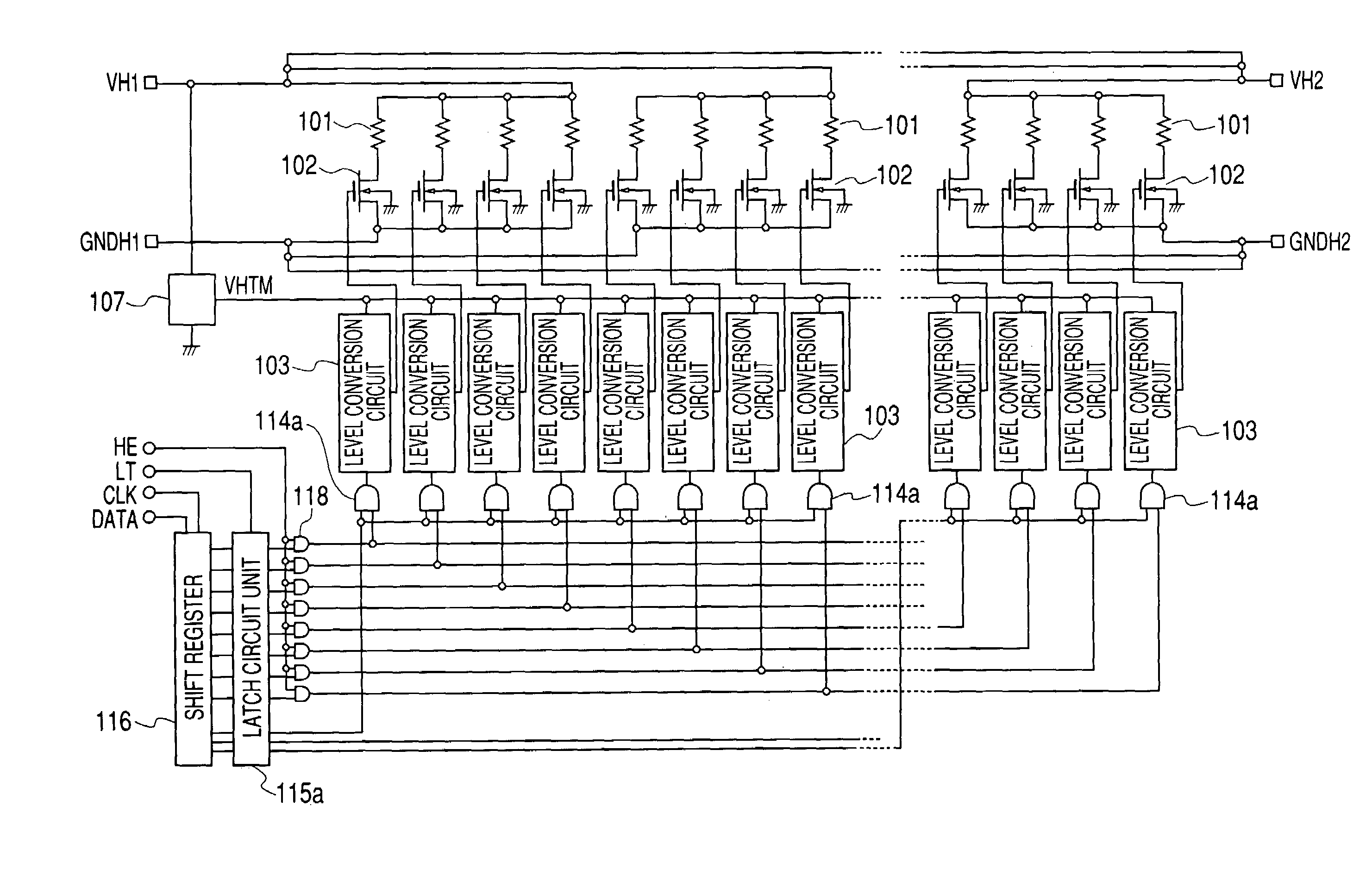
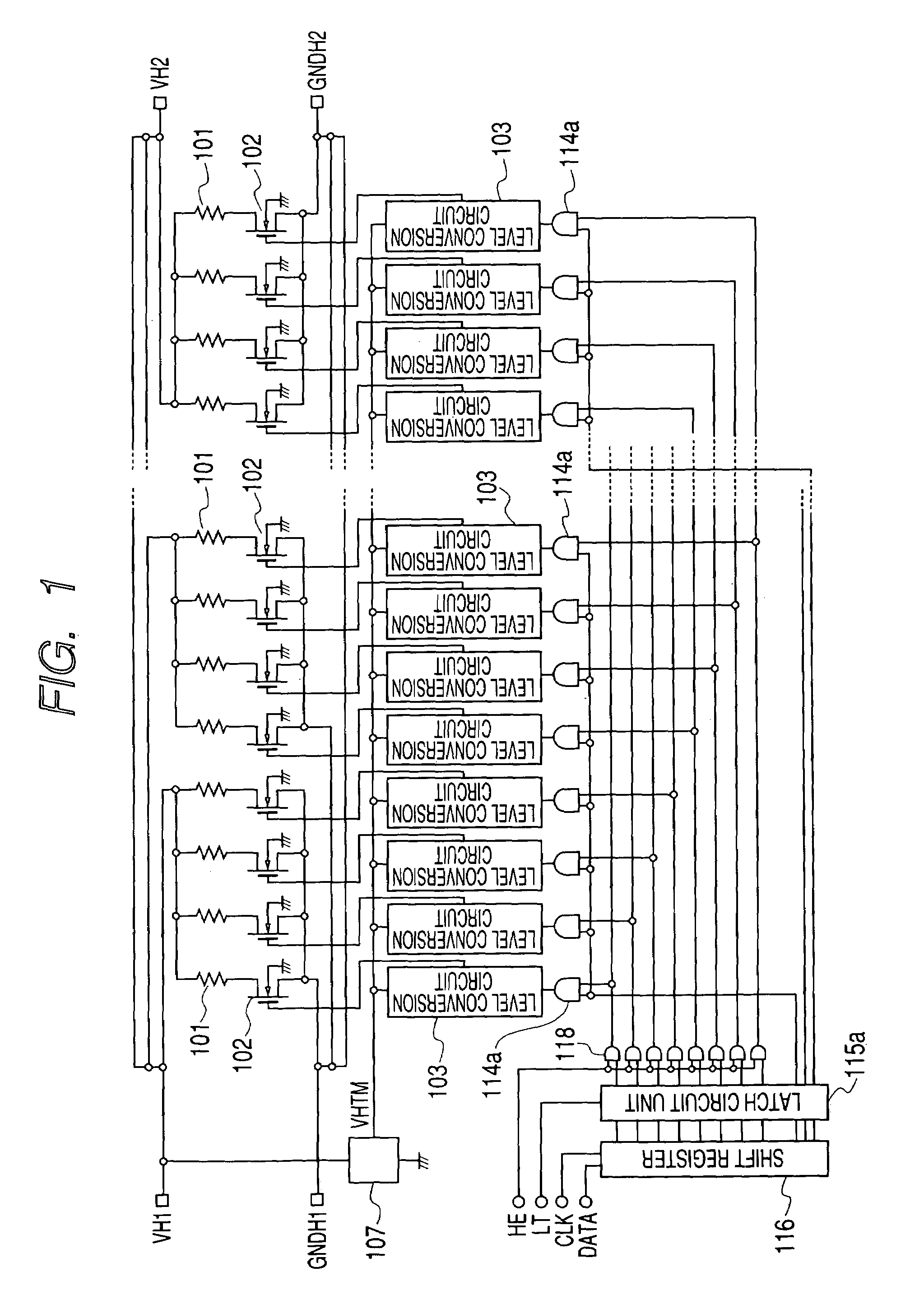
[0050]Next, preferred embodiments of the present invention will be described with reference to the drawings. As described below, a liquid ejection head is an ink jet recording head used for an ink jet recording, and the case where a heater for generating heat by the current is used as a recording element will be described. In the present invention, where a number of heaters are arranged on a semiconductor substrate, and further, a drive logic circuit for driving these heaters according to a signal inputted from the outside and power transistors are also arranged on the semiconductor substrate, a number of heaters are divided into several segments in order to reduce the influence arising from the difference of a wiring resistance on the semiconductor substrate. Each segment includes a plurality of heaters and power transistors corresponding to these heaters one for one base.

[0051]First, to understand the present invention at full length, a wiring resistance arising ...

second embodiment

(Second Embodiment)

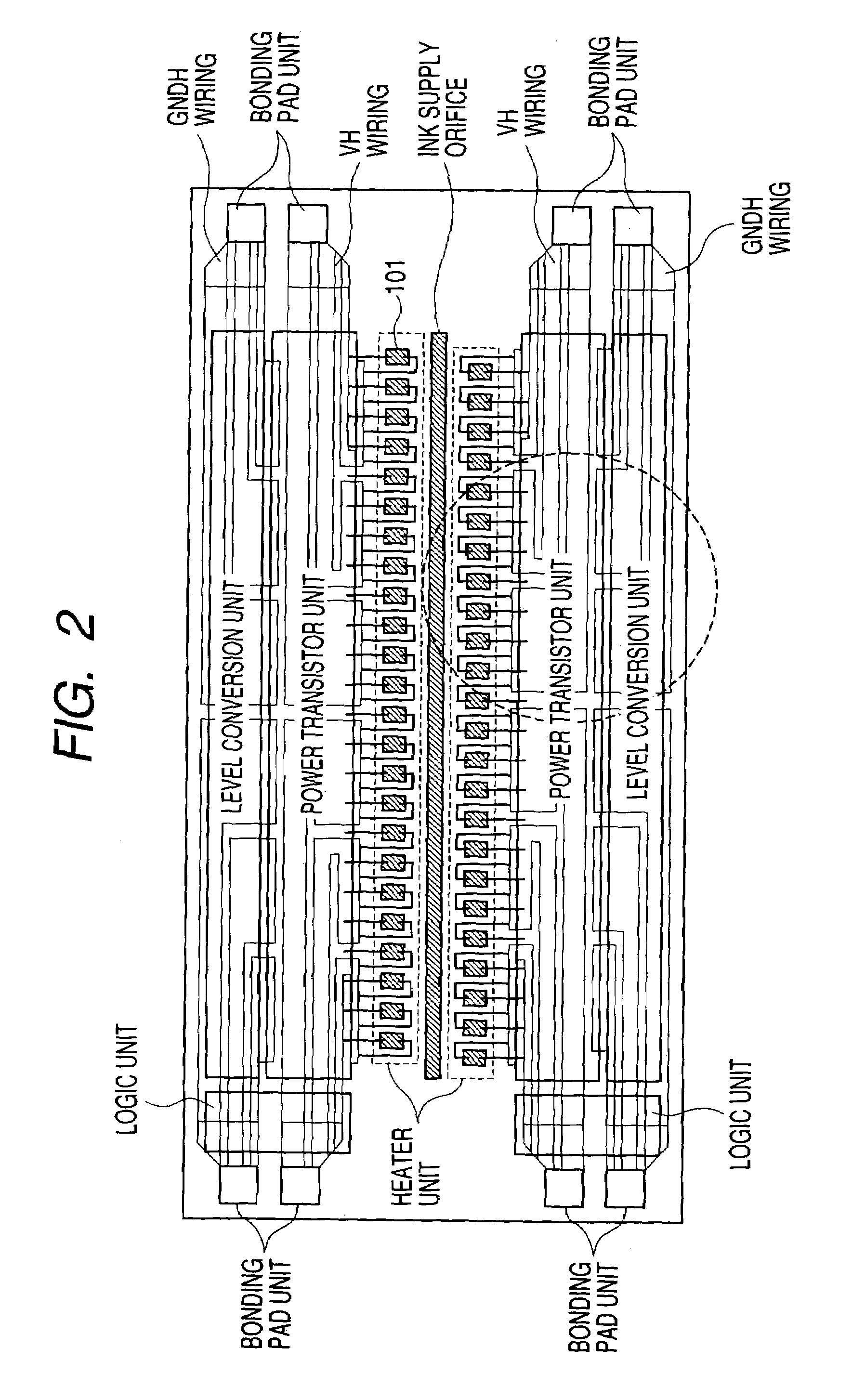
[0081]The present embodiment is characterized by having three wiring layers. The description of the like structure as the first embodiment will be omitted. Showing a layout of a VH wiring and a GNDH wiring of the present embodiment is FIG. 16. FIG. 16 shows a structure, which mounts a recording head drive circuit on both sides for an ink supply orifice. The VH wiring is provided so as to pass through above the power transistor unit (forming region of the power transistor 102) by using a second layer aluminum wiring or a third layer aluminum wiring. Further, the GNDH wiring is also provided so as to pass through above a level conversion unit (forming region of the level conversion circuits) by using the second layer aluminum wiring or the third layer aluminum wiring. In the present embodiment, the wiring connected to the heater arranged close to a bonding pad unit is formed by the second layer aluminum wiring, and the wiring connected to the heater far from the bon...


PUM


Abstract

A semiconductor device constituting a liquid ejection head for ejecting a liquid such as an ink, comprising a segment having a plurality of pairs of recording element and driving element, wherein a first wiring for mutually connecting a first terminal of each driving element arranged within the same segment is formed on a first wiring layer on a semiconductor substrate, and a second terminal of the driving element and a first terminal of the recording element are connected on one for one base, and a second terminal of the recording element is connected to a power source wiring formed by the wiring layer different from the first wiring layer, and an auxiliary wiring for mutually connecting the second terminal of the recording element with the same segment is formed by the first wiring layer, thereby eliminating and suitably adjusting the irregularity of wiring resistance values within the segment.

Description

BACKGROUND OF THE INVENTION[0001]1. Field of the Invention[0002]The present invention relates to a semiconductor device for a liquid ejection head used for constituting a liquid ejection head for ejecting a liquid such as, for example, ink, and a liquid ejection head and a liquid ejection apparatus using such a semiconductor device for a liquid ejection head.[0003]2. Related Background Art[0004]A liquid ejection head for ejecting a liquid from an ejection orifice issued as a recording head of an ink jet system by using, for example, ink as a liquid and controlling an ejection of ink according to recording signals and adhering the ink on a recording medium. Further, the liquid ejection apparatus comprising such a liquid ejection head is, for example, applied as an ink jet recording apparatus.[0005]Here, describing a recording method of the ink jet system, the ink jet recording method (liquid jetting recording method) is capable of a high speed recording to the extent that a generatio...

Claims


Application Information

Patent Timeline
Patent Type & Authority Patents(United States)
IPC IPC(8): B41J2/05B41J2/14
CPCB41J2/04531B41J2/04541B41J2/04543B41J2/0455B41J2/0458B41J2/14072
Inventor OOMURA, MASANOBU
Owner CANON KK
Why Eureka
Try Eureka