Cutting tool

a cutting tool and cutting edge technology, applied in the field of cutting tools, can solve the problems of reducing the life of the cutting tool, reducing cutting precision, and greatly deteriorating the cutting edge performance, and achieves the effects of improving cutting performance, superior durability, and reducing the degree of irregularity in the shape of the cutting edg

Inactive Publication Date: 2009-04-02
AISIN AW CO LTD
View PDF13 Cites 0 Cited by
  • Summary
  • Abstract
  • Description
  • Claims
  • Application Information

AI Technical Summary

Benefits of technology

[0016]Almost all conventional diamond tips serving as cutting edges employ diamond particles having a comparatively large average particle diameter (D50) between 2 μm and 10 μm, whereas in the present invention, the employed diamond tip is formed by sintering extremely small-diameter diamond particles having an average particle diameter (D50) between 0.2 μm and 1.6 μm. Therefore, even when diamond particles become dislodged in an identical proportion, the degree of irregularity in the shape of the cutting edge is smaller in the present invention compared to the related art. Hence, when used to cut the lead-free copper-based bearing alloy described above, the cutting tool of the present invention exhibits superior durability and an improved cutting performance in comparison with a conventional cutting tool.

Problems solved by technology

However, with the recent increased awareness of environmental concerns, alloys containing lead as a component have been shunned, and demand for lead-free copper-based bearing alloys that do not contain lead has increased.
JP-A-2007-54945), the cutting performance of the cutting edge is greatly deteriorated greatly in comparison to the cutting performance during cutting of a conventional lead-containing copper-based bearing alloy.
This deteriation in cutting performance can lead to problems such as a reduction in cutting precision and a reduction in the life of the cutting tool.

Method used


Image

  • Cutting tool
  • Cutting tool
  • Cutting tool

Examples


first embodiment

[0029]A cutting tool according to an embodiment of the present invention will be described using FIGS. 1 to 4.

[0030]A cutting tool 1 according to this embodiment is a cutting tool for cutting a lead-free copper-based bearing alloy comprising 75 to 95% by mass Cu, 1 to 15% by mass Bi, and 1 to 10% by mass hard particles comprising metal phosphide, boride, or carbide.

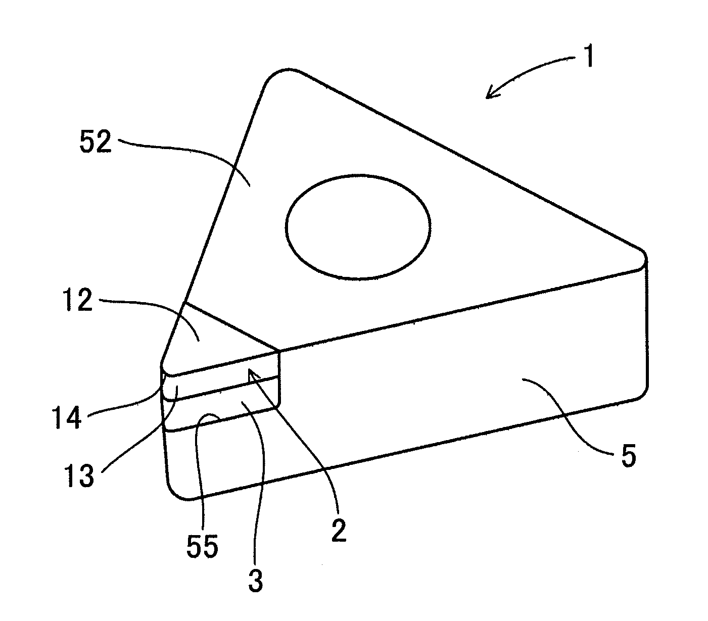
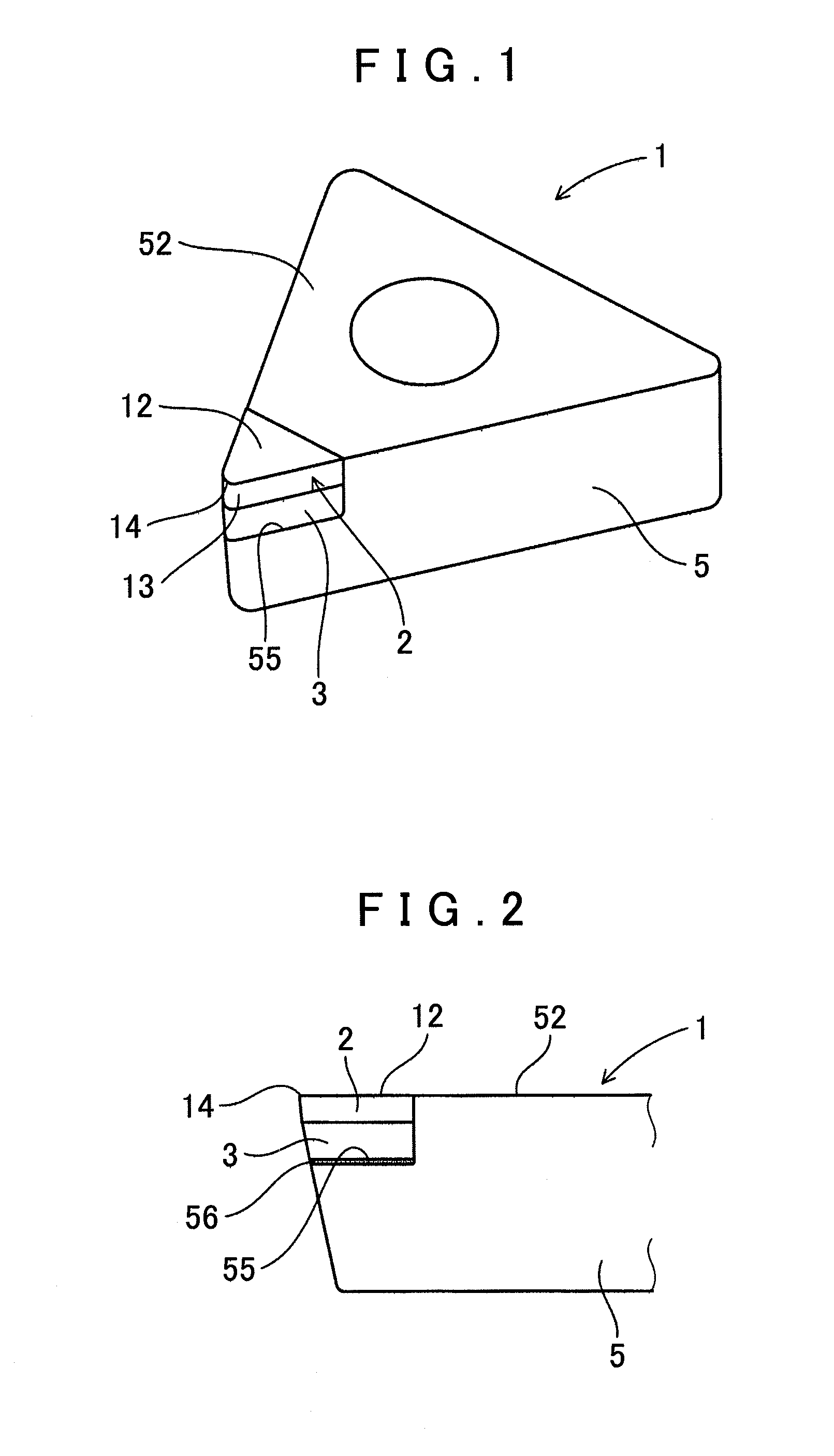
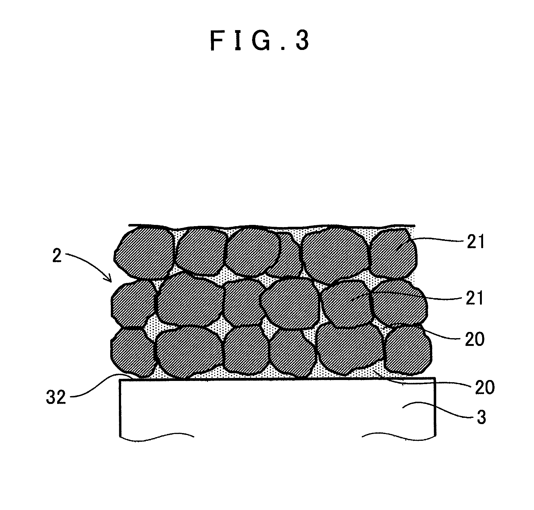
[0031]The cutting tool 1 includes a rake surface 12, a clearance surface 13, and a cutting edge 14 formed on a line of intersection between the rake surface 12 and clearance surface 13, and a tip end site including the cutting edge 14 comprising a diamond tip 2. The diamond tip 2 comprises a sintered body formed by sintering diamond particles 21 having an average particle diameter (D50) between 0.2 μm and 1.6 μm.

[0032]The cutting tool 1 will now be described in detail.

[0033]As shown in FIGS. 1 and 2, the cutting tool 1 of this embodiment is formed by moving back an angle portion on a rake surface 52 side of a substantiall...


PUM

PropertyMeasurementUnit
particle diameteraaaaaaaaaa
clearance angleaaaaaaaaaa

Abstract

A cutting tool for cutting a lead-free copper-based bearing alloy containing 75 to 95% by mass Copper(Cu):, 1 to 15% by mass Bismuth(Bi), and 1 to 10% by mass hard particles comprising metal phosphide, boride, or carbide. The Cutting tool includes a rake surface, a clearance surface, and a cutting edge formed on a line of intersection between the rake surface and the clearance surface. A tip end site including the cutting edge comprises a diamond tip, and the diamond tip comprises a sintered body formed by sintering diamond particles having an average particle diameter (D50) between 0.2 μm and 1.6 μm. The cross section of the cutting edge preferably has a curved surface shape with a radius of curvature between 10 μm and 50 μm.

Description

INCORPORATION BY REFERENCE[0001]The disclosure of Japanese Patent Application No. 2007-253192 filed on Sep. 28, 2007, including the specification, drawings and abstract is incorporated herein by reference in its entirety.BACKGROUND OF THE INVENTION[0002]1. Field of the Invention[0003]The present invention relates to a cutting tool for cutting a lead-free copper-based bearing alloy that does not contain lead.[0004]2. Description of the Related Art[0005]Copper alloys containing lead (Pb) are widely used conventionally as a copper-based bearing alloy employed as a slide bearing (see Japanese Patent Application Publication No JP-A-H7-179964). However, with the recent increased awareness of environmental concerns, alloys containing lead as a component have been shunned, and demand for lead-free copper-based bearing alloys that do not contain lead has increased.[0006]In light of this background, a lead-free copper-based bearing alloy comprising 75 to 95% by mass Copper(Cu), 1 to 15% by ma...

Claims


Application Information

Patent Timeline
Patent Type & Authority Applications(United States)
IPC IPC(8): B26D3/00
CPCB23B27/145B23B2200/125Y10T407/23B23B2226/315B23B2200/245
Inventor MOTOMURA, JIROISHIKAWA, KOICHIYAMAYA, KENICHI
Owner AISIN AW CO LTD
Why Eureka
Try Eureka