
Simple high accuracy high energy calorimeter

a calorimeter and high-efficiency technology, applied in the field of measuring energy, can solve the problems of high-pressure pump itself, high cost of high-pressure pump, water-use calorimeter, etc., and achieve the effects of limiting the absorption of ambient environmental thermal energy, and reducing the cost of high-pressure pumps

Inactive Publication Date: 2006-10-24
THE BOEING CO
View PDF24 Cites 14 Cited by
  • Summary
  • Abstract
  • Description
  • Claims
  • Application Information

AI Technical Summary

Benefits of technology

This design enhances measurement accuracy, reduces operational and maintenance costs, and avoids the inaccuracies associated with water-based systems, while allowing the calorimeter to withstand high power radiation without cooling during measurements.

Problems solved by technology

However, currently known calorimeters that use water to measure the temperature change of the body include drawbacks.
This increases surface area for heat transfer from the body of the calorimeter to the water, but this also introduces a pressure drop in the water flow because of constriction of the channels.
The high pressure pump itself is expensive.
However, maintaining water chemistry within desirable limits to reduce contamination and corrosion introduces further costs because water chemistry maintenance is extremely labor-intensive.
Use of DI water and fungicide increases costs even further.
Further, if channel blockages become severe enough, there may be areas of the calorimeter that experience restricted water flow, thereby causing inaccurate measurement and / or elevated local temperatures at which the equipment may fail.
For example, water is subject to self-heating due to the friction of the water being pumped at high pressure through the intricate channels.
This unintended self-heating of the water results in a temperature rise in the water that is not caused by the input radiation and therefore is a source of inaccuracy in the measurement of input radiation.
Inaccuracies in measurement of water flow rates also cause inaccuracies in measurements of the input radiation.
For example, when water is forced under high pressure to flow through the calorimeter body, it can set up turbulence in the flow that will introduce false readings in the flow meter.
Furthermore, there is some energy left in the calorimeter body that is not transferred to the water and therefore is not measured by the thermometer.
This residual energy will then introduce inaccuracies in the measurement of the total energy of the radiation source.

Method used


Image

  • Simple high accuracy high energy calorimeter
  • Simple high accuracy high energy calorimeter
  • Simple high accuracy high energy calorimeter

Examples


Embodiment Construction

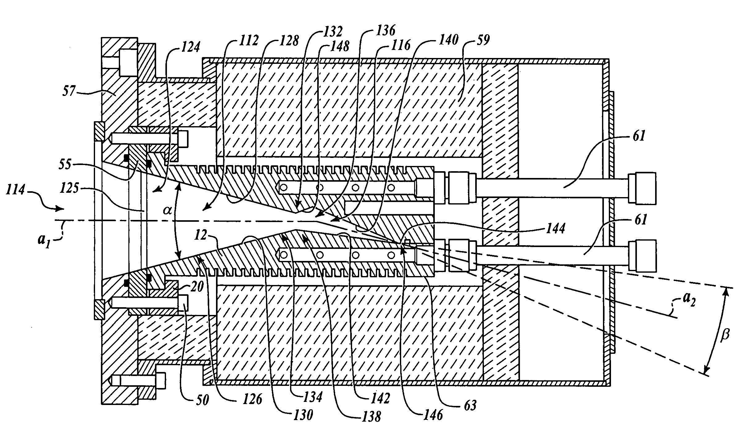
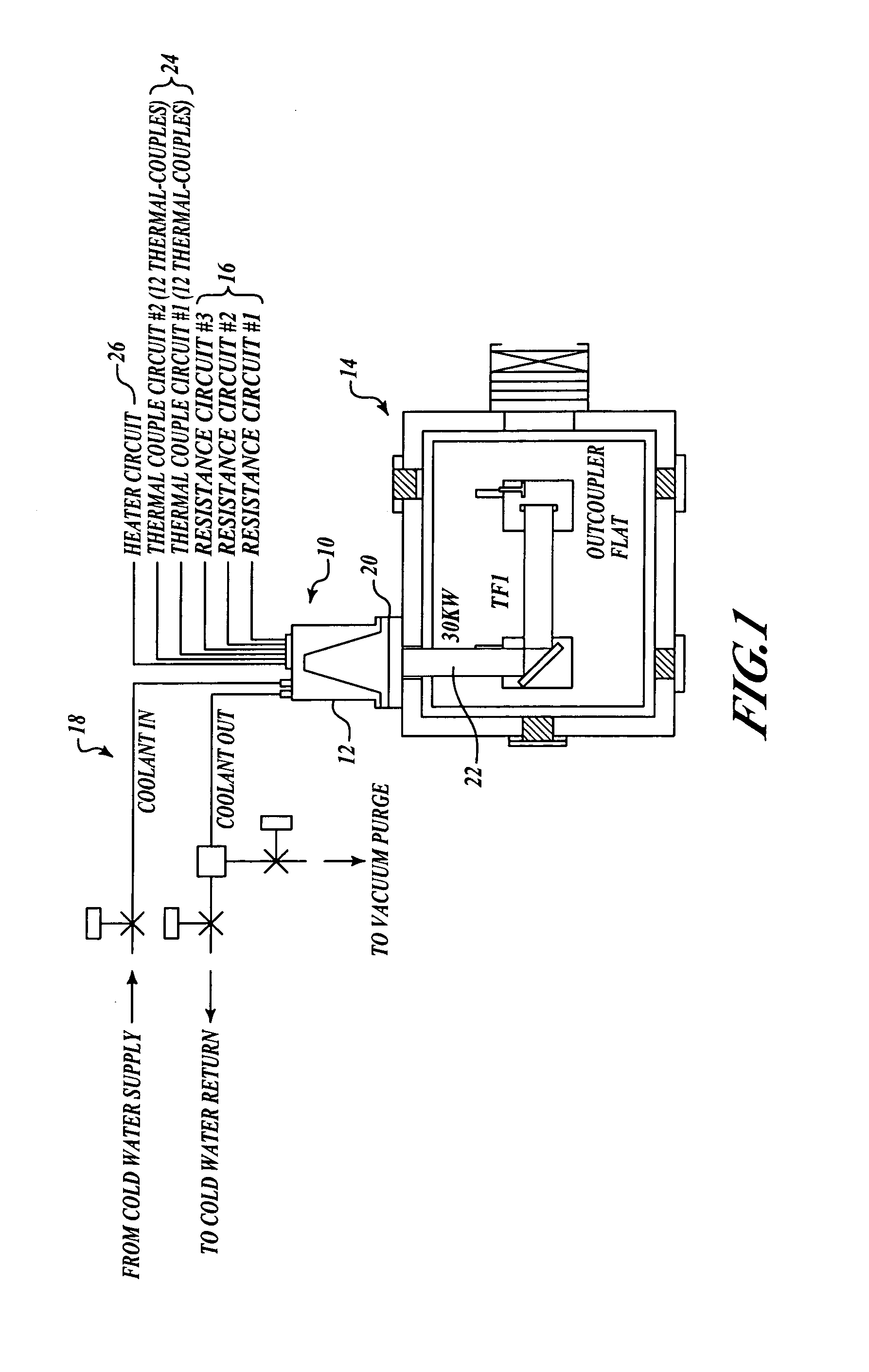
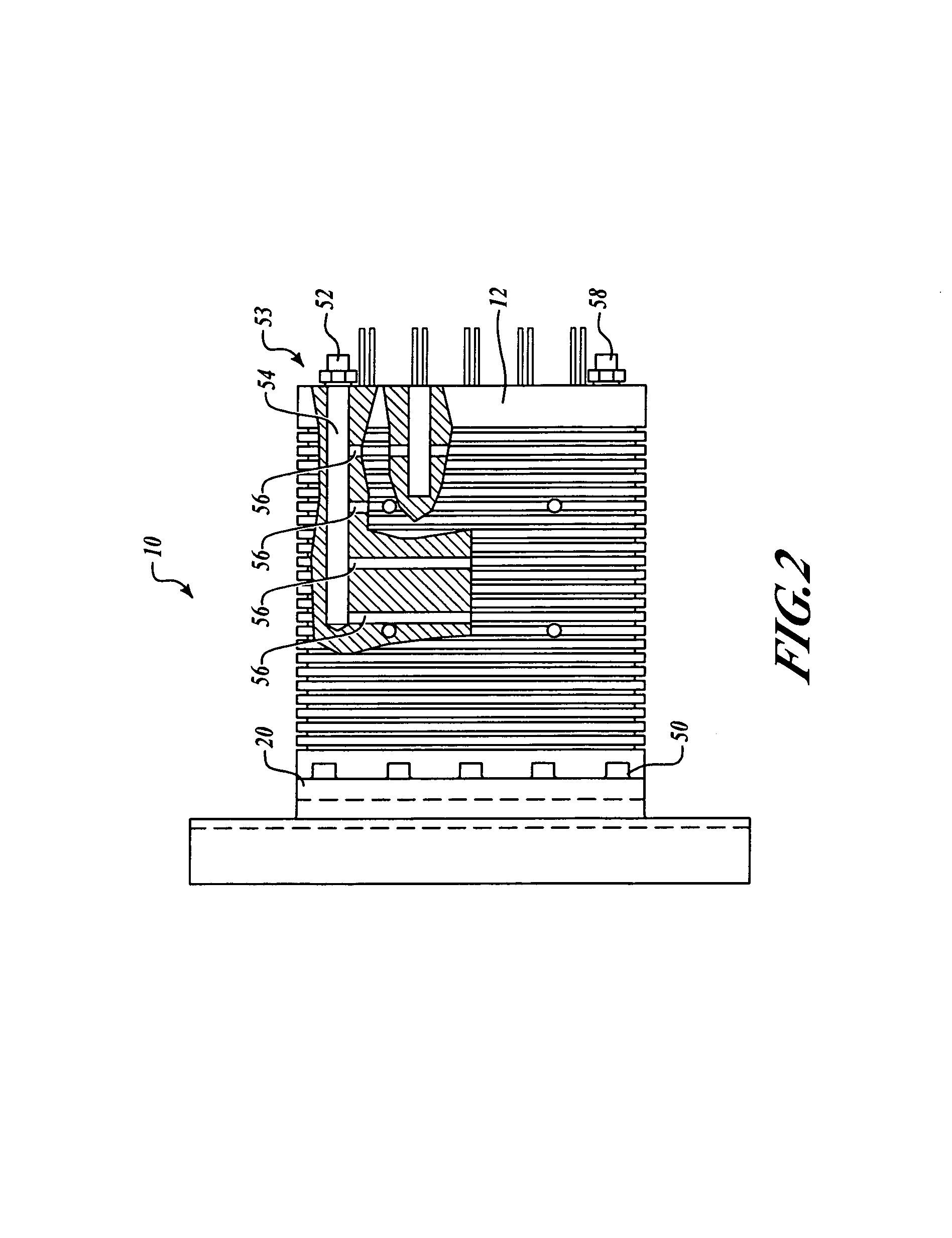
[0029]By way of overview and referring to FIG. 1, an exemplary high energy calorimeter 10 is able to withstand high power radiation 22, accurately measures substantially all of the energy of the radiation 22, and is inexpensive to fabricate, operate, and maintain. According to an exemplary embodiment of the present invention, the calorimeter 10 includes a body 12 configured to capture radiation 22 generated by a source 14 of the radiation 22, such as without limitation a laser, and absorb energy from the captured radiation 22. A temperature sensor system 16 is attached in thermal communication with the body 12, and the temperature sensor system 16 is configured to detect temperature changes of a substantial portion of the body 12. The absorption of the captured radiation 22 by the body 12 causes the temperature changes. A liquid or gaseous cooling system 18 is configured to provide post-measurement cooling of the body 12 from temperatures elevated due to absorption of the captured r...


PUM

PropertyMeasurementUnit
wavelengthaaaaaaaaaa
mode sizeaaaaaaaaaa
mode sizeaaaaaaaaaa

Abstract

An exemplary calorimeter includes a body configured to capture radiation generated by a source of the radiation, such as without limitation a laser, and absorb energy from the captured radiation. The calorimeter is simple to manufacture, operate, and maintain and is compact, highly accurate, able to withstand high power beams, and self-calibrating. NIST traceable electrical wires are used for the measurement. No fluids are used during measurements of the input radiation. A simple built in fluid or gaseous cooling system may be used post-measurement to reset the calorimeter temperature back to ambient for repeated measurement capability.

Description

RELATED APPLICATION[0001]This patent application is related to a concurrently-filed U.S. patent application Ser. No. 10 / 720,772 entitled “High Performance System and Method For Capturing and Absorbing Radiation”, the contents of which are hereby incorporated by reference.FIELD OF THE INVENTION[0002]The present invention relates generally to measuring energy and, more specifically, to measuring energy of radiation.BACKGROUND OF THE INVENTION[0003]Many modern devices, such as high-energy lasers and high powered-lamps like solar simulator lamps, are capable of putting out high levels of energy in the form of radiation. In certain circumstances, it is desirable to capture and absorb all or part of the output beam of such devices. For example, capturing a portion of the output beam may be desirable when the full output of the device provides too much energy for a desired application. Whether capturing all or part of a beam, if such a device simply captures and absorbs the output energy i...

Claims


Application Information

Patent Timeline
Patent Type & Authority Patents(United States)
IPC IPC(8): G01K17/00G01J5/00G01N25/20
CPCG01K17/00
Inventor EIGLER, LYNNE C.TAM, YAN S.KOHANZADEH, YOUSSEF
Owner THE BOEING CO
Learn More