High-pressure fan

a fan and high-pressure technology, applied in the direction of machines/engines, stators, liquid fuel engines, etc., to achieve the effect of reducing space requirements, high benefit, and reducing structur

Inactive Publication Date: 2006-10-24
HOWDEN AXIAL FANS
View PDF15 Cites 3 Cited by
  • Summary
  • Abstract
  • Description
  • Claims
  • Application Information

AI Technical Summary

Benefits of technology

[0009]One advantage of the intermediate channel structure of the invention is a compact, space-saving structure that reduces the need for space on the site of use as well as freight costs when transporting the fan to the site of use. An especially high benefit is achieved, when the fan needs to be soundproofed with a soundproof enclosure, since then a lower structure also reduces the material costs of the enclosure.
[0010]An intermediate channel integrated to the base also adds to the rigidity of the entire fan, thus lowering the vibration level and extending the operating life. In addition to the rigidity, a lower centre of gravity is also obtained for the structure, whereby these two properties together shift the specific frequencies of the base structure to a higher frequency range, in other words, provide a wider rotation rate activity.
[0011]The fan can now also be mounted on vibroinsulators instead of directly on a concrete base, which would otherwise be obligatory due to the critical specific frequencies. The vibroinsulators, in turn, enable a freer placement of the fan, i.e. not only on the ground floor of a building as is usually the case when the fan is mounted directly on a concrete base.

Problems solved by technology

Even though this known high-pressure fan structure provides the significant advantages listed above, problems are still caused by said intermediate channel that requires a lot of space and causes vibration especially at high rotation rates.

Method used


Image

  • High-pressure fan
  • High-pressure fan

Examples


Embodiment Construction

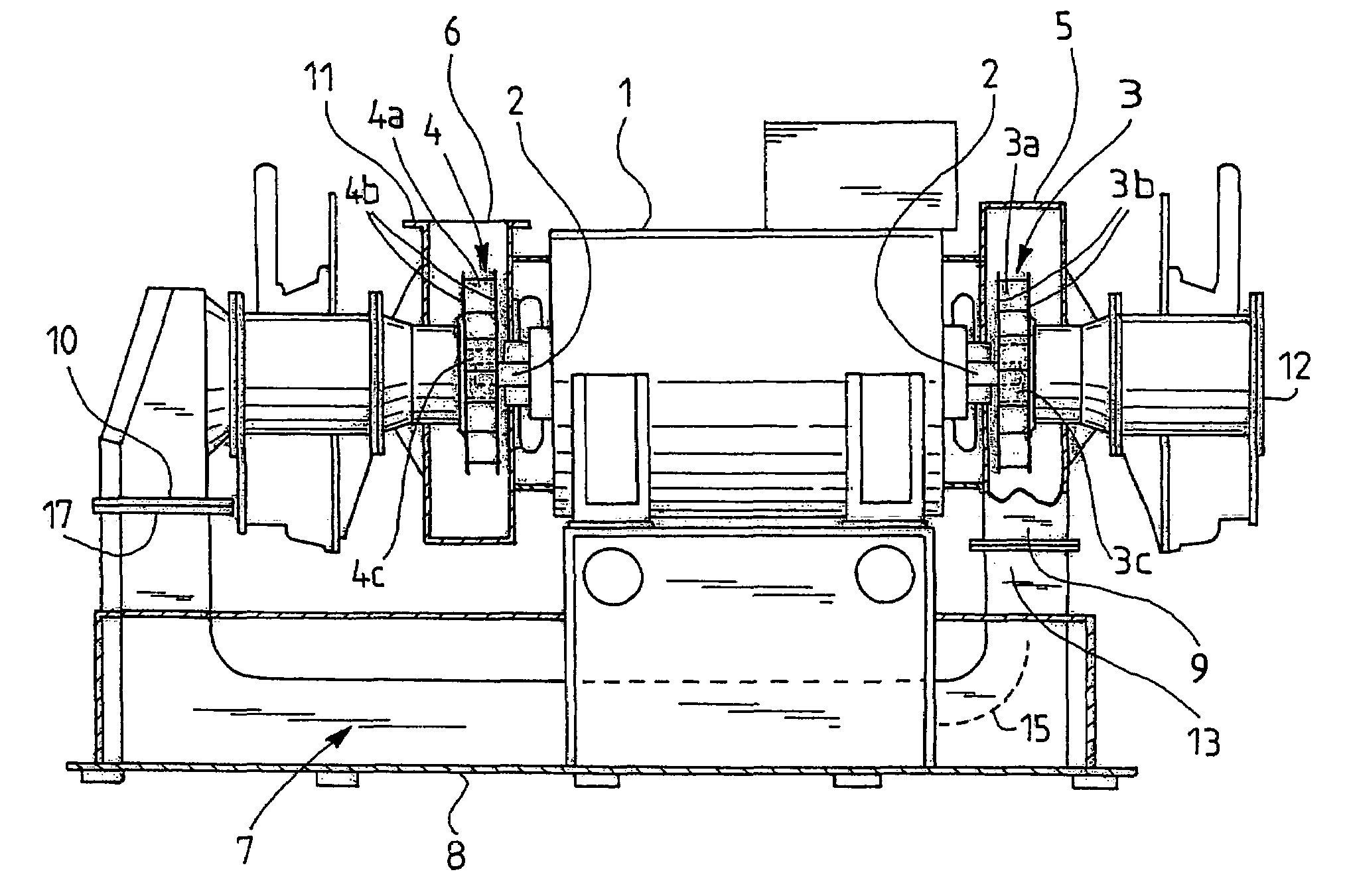
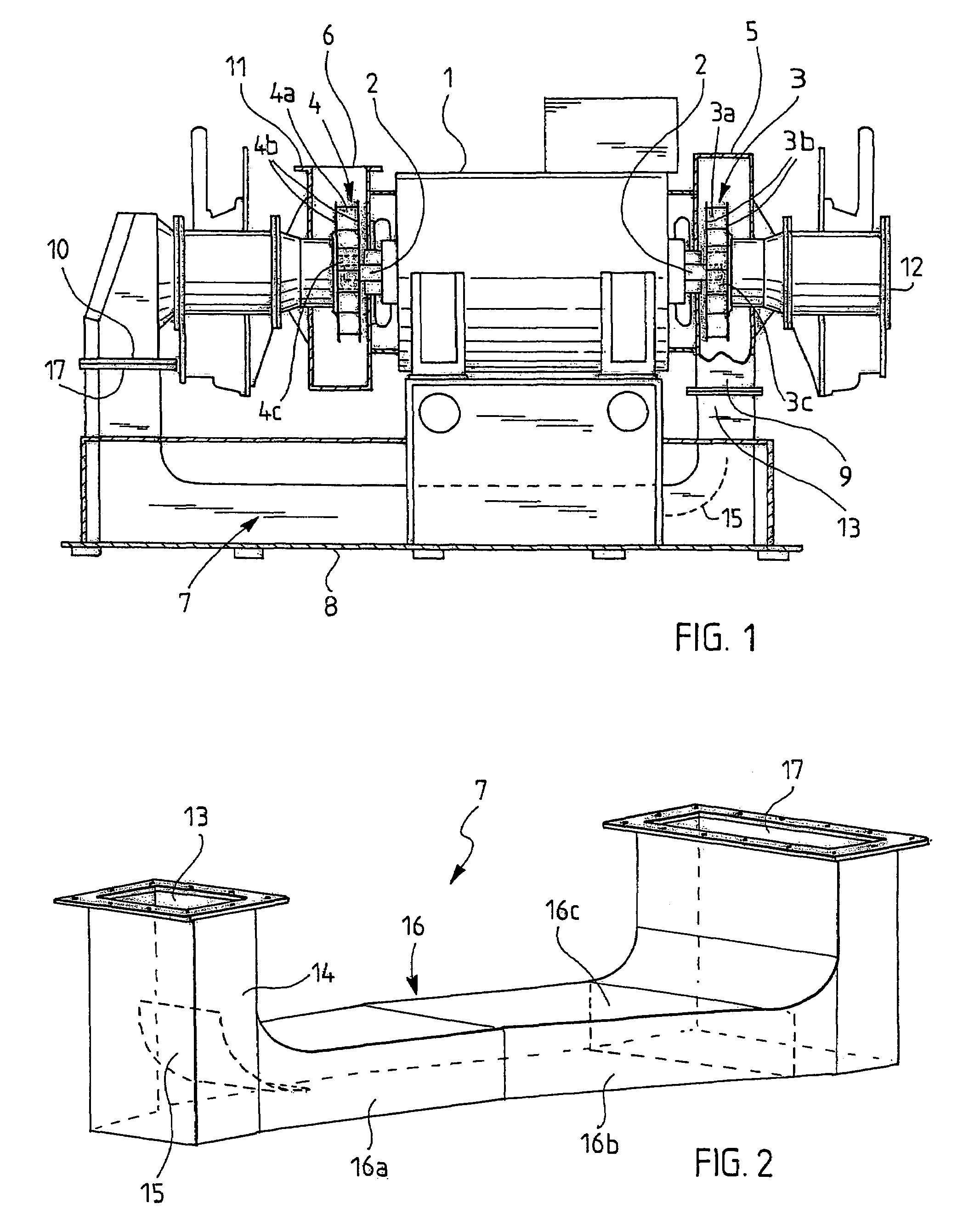
[0015]FIG. 1 shows a high-pressure fan having an electric motor 1 with a rotor shaft 2 that goes through it, i.e. a shaft with its ends protruding from both sides of the motor, as its driving power source. A light blade wheel 3 and 4 made at least mainly of a carbon fibre-based composite material, i.e. at least the blades 3a, 4a and the end plates 3b, 4b are made of the material, is directly mounted without separate bearings to both ends of this shaft 2. The hub structure 4c of the blade wheel can also be made of some other material, such as steel. This direct mounting means that only the bearings of the electric motor are used in the mounting of the entire structure described above. The blade wheels 3 and 4 are surrounded by fan housings 5 and 6, and a pressure opening 9 of the first housing 5 is connected by an intermediate channel 7 to a suction opening 10 of the second housing. The pressure opening of the second housing is indicated with reference numeral 11 and the suction open...


PUM


Abstract

The invention relates to a high-pressure fan which comprises an electric motor provided with a shaft that goes through it; blade wheels which are mainly made of a carbon fibre-based composite material, arranged on both sides of the electric motor and mounted directly on the shaft of the electric motor; fan housings surrounding the blade wheels; and an intermediate channel which connects a pressure opening of one fan housing to a suction opening of the other fan housing, the intermediate channel being integrated into the base structure of the high-pressure fan.

Description

[0001]This application is the US national phase of international application PCT / FI02 / 00885 filed in English on 11 Nov. 2002, which designated the US. PCT / FI02 / 00885 claims priority to FI Application No. 20012184 filed 12 Nov. 2001. The entire contents of these applications are incorporated herein by reference.BACKGROUND OF THE INVENTION[0002]The invention relates to a high-pressure fan which comprises an electric motor provided with a shaft that goes through it; blade wheels which are mainly made of a carbon fibre-based composite material, arranged on both sides of the electric motor and mounted directly on the shaft of the electric motor; fan housings surrounding the blade wheels; and an intermediate channel which connects a pressure opening of one fan housing to a suction opening of the other fan housing, the intermediate channel being integrated into the base structure of the high-pressure fan and located substantially below the electric motor and the blade wheels mounted to it....

Claims


Application Information

Patent Timeline
Patent Type & Authority Patents(United States)
IPC IPC(8): F04D25/06F04D25/16F04D17/12F04D29/02F04D17/14F04D29/44
CPCF04D17/122F04D25/16F04D29/441F04D29/601F04D17/164F04D25/166
Inventor SARIN, DANLINDROOS, KARETALLGREN, JONISANDBERG, ILPPOKUOKKANEN, JARIBLAFIELD, JUKKAMAJAMAKI, OLLI
Owner HOWDEN AXIAL FANS
Why Eureka
Try Eureka