Electron microscope

a technology of electron microscope and microscope, which is applied in the direction of instruments, material analysis using wave/particle radiation, nuclear engineering, etc., can solve the problems of low image contrast of enlarged specimen images, difficulty in discriminating astigmatism correction directions, and low image contrast of images, so as to improve the operation capability of electron microscope and high reproducibility

Active Publication Date: 2006-10-24
HITACHI HIGH-TECH CORP
View PDF8 Cites 12 Cited by
  • Summary
  • Abstract
  • Description
  • Claims
  • Application Information

AI Technical Summary

Benefits of technology

[0009]A fourth problem to be solved by this invention is that in the electron microscope for performing auto focusing and auto astigmatism correction, the presence of defocusing or focus offset and astigmatic aberration degrades or lowers the contrast of an enlarged specimen image, with the result that positional alignment with a correct focus correction position and astigmatism correction position is prevented. Accordingly, a still another object of this invention is to provide an electron microscope capable of supplying suitable objective lens coil current and stigmator coil current even when the contrast of an image is low owing to the focus offset and astigmatic aberration.
[0022]According to the present invention, by automating the astigmatism correction, conventionally carried out manually, in combination with the focus correction, the operator can be allowed for obtaining an image of a quantitatively given astigmatic difference amount with high reproducibility without resort to knowing status of astigmatism and focus and operational capability of the electron microscope can be improved.

Problems solved by technology

But, in case the astigmatism correction is tried under a greatly defocused condition, the enlarged specimen image has a low image contrast and the astigmatism correction direction becomes very difficult to discriminate.
On the other hand, when the focus correction is performed under a condition that a large astigmatic aberration exists, the image contrast of an image is lowered similarly and determination of an exact focus position is difficult to achieve.
In other words, when only the focus correction is completed and the astigmatism remains, the enlarged specimen image becomes blurred, giving rise to degradation of image quality and inaccuracy of analytical position.
In operator-based adjustment, the operator must adjust three of focus, X-direction astigmatism and Y-direction astigmatism at a time while deciding the contrast of image and for an operator having poor experience, the adjustment is complicated and sophisticated and difficult to perform.
A second problem to be solved by this invention is that when the astigmatism is large, the image blur is aggravated and a sufficient image sharpness coefficient cannot be obtained.
A third problem to be solved by this invention is that when objective lens coil current and stigmator coil current are adjusted toward an exact focus position with an electron microscope for performing auto focusing and auto astigmatism correction, focusing to the exact focus position cannot be done properly owing to hysteresis of a ferromagnetic material used for the lens coil.
There is also a problem that when an image average integration filter is used in order to speed up the image capture or pickup and improve the S / N ratio, past information is superimposed on an image and as a result, an offset is caused in correction current.

Method used


Image

  • Electron microscope
  • Electron microscope
  • Electron microscope

Examples


first embodiment

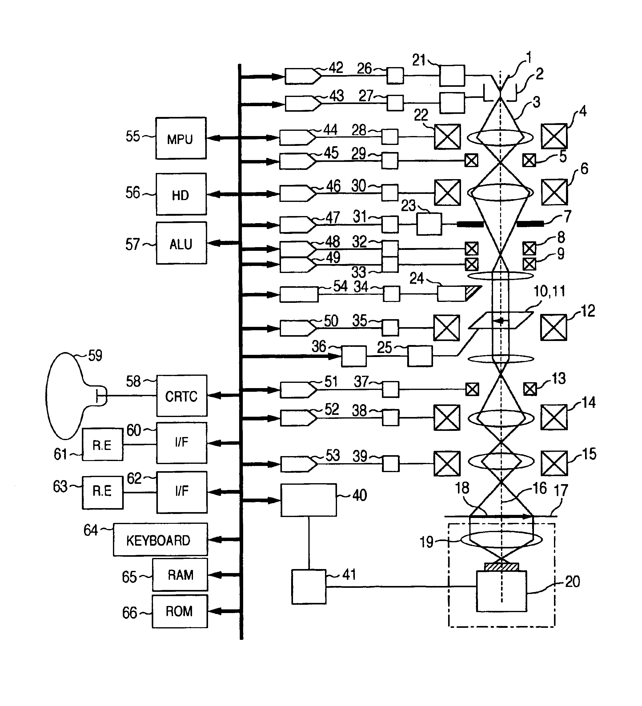
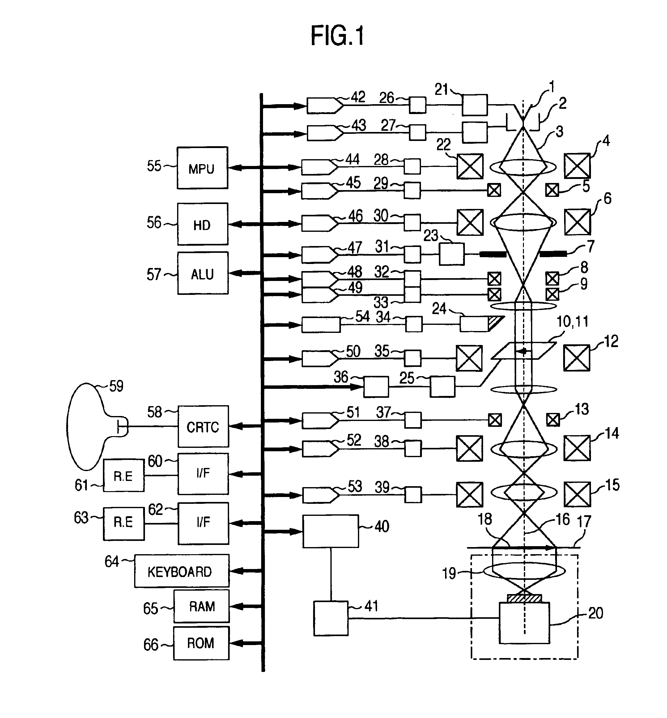
[0096]By making reference to a flowchart in FIG. 6, the present invention will be described. In the present embodiment, the electron microscope shown in FIG. 1 is used to decide whether the focus of an enlarged specimen image is defocused and at the same time whether astigmatism exists and to perform automatic correction, thereby solving the first problem.

[0097]In step S101, the use of the electron microscope is started. A desired specimen 11 is mounted to the specimen stage 10 and is then inserted to the electron microscope. In step 102, a desired magnification is set by means of the magnification switching rotary encoder 61 shown in FIG. 1. Concurrently, data of electron beam source precedently recorded in the ROM 66 is called out and processed by the microprocessor 55 so that a current may be delivered out of a DAC 42 and a stabilizer 26. This current is supplied to the emitter 1 via a cathode power supply 21 and electrons are emitted from the emitter 1. As for acceleration volta...

second embodiment

[0107]Referring now to a flowchart in FIG. 11, this invention will be described. The present embodiment makes a decision as to whether the focus of an enlarged specimen image is defocused and as to whether an astigmatic aberration exists so as to perform automatic correction, thereby solving the first problem. The flowchart in FIG. 11 shows algorithm capable of determining an image sharpness coefficient dependent on angular directions with a view to simplifying algorithm and speeding up operation.

[0108]In step 201, the use of the electron microscope is started. A desired specimen 11 is mounted to the specimen stage 10 and is then inserted to the electron microscope. In step S202, setting of observation magnification, respective lens coil currents, respective deflection coil currents, focus correction parameters and astigmatism correction parameters is carried out. Step S202 corresponds to the step S102 explained in connection with FIG. 7.

[0109]In step S203, the focus is changed. Thi...

third embodiment

[0119]Referring now to a flowchart in FIG. 12, this invention will be described. In this embodiment, a pixel mean value of an image is determined to capture a change in image contrast during astigmatism correction, so that under a condition that a large astigmatic aberration exists and an enlarged specimen image becomes blurred seriously, the astigmatism correction can be effected, thereby solving the second problem. The FIG. 12 flowchart is inserted between the steps S102 and S103 in FIG. 6 or between the steps S202 and S203 in the FIG. 11 flowchart in order to make the focus and the astigmatism of the enlarged specimen image substantially coincident to each other.

[0120]After the initial setting in the step S102 in FIG. 6 or the initial setting in the step S202 in FIG. 11 has been completed, the program proceeds to step S301 in FIG. 12. In the step S301, the focal position in the electron microscope is changed and image sharpness coefficients are calculated in step S302. In the pre...


PUM

PropertyMeasurementUnit
electron microscopeaaaaaaaaaa
currentaaaaaaaaaa
thresholdaaaaaaaaaa

Abstract

In an electron microscope, focus correction is carried out automatically, an astigmatic difference amount is displayed and astigmatism correction is executed quantitatively. Enlarged specimen images obtained by irradiating an electron beam on a specimen while changing excitation currents of an objective lens and of a stigmator coil are picked up by a capturing unit comprised of an optical lens and a capturing device and image sharpness coefficients are calculated by means of an arithmetic logic unit. A suitable astigmatism correction direction is chosen on the basis of an angular component value of the obtained image sharpness coefficients and then, a correction excitation current is supplied to a stigmator coil to correct astigmatism and a correction excitation current is supplied to an objective lens coil to perform focus correction.

Description

BACKGROUND OF THE INVENTION[0001]The present invention relates to electron microscopes and more particularly, to an electron microscope capable of automatically adjusting the focus of an electron lens and astigmatism of an electron beam.[0002]Conventionally, in observing, measuring, analyzing and searching a field of view of an enlarged specimen image with an electron microscope, an operator participates in performing focusing and astigmatism adjustment while directly watching the enlarged specimen image. In adjusting focus and astigmatism, while the focus correction is carried out in the direction of height of a specimen (referred to as Z direction), the astigmatism correction is carried out in respect of astigmatic aberrations in 0° and 90° directions (X direction) of the specimen and in respect of astigmatic aberrations in 45° and 135° directions (Y direction) of the specimen and therefore adjustments in three directions in total must be accomplished. Namely, when only the focus ...

Claims


Application Information

Patent Timeline
Patent Type & Authority Patents(United States)
IPC IPC(8): G01N23/00G21K7/00H01J37/22G01N23/04H01J37/153H01J37/21H01J37/26H01J37/28
CPCG01N23/04H01J37/26H01J2237/1532H01J2237/216
Inventor INADA, HIROMI
Owner HITACHI HIGH-TECH CORP
Why Eureka
Try Eureka