Method and system for flow control with fluidic oscillators

Active Publication Date: 2006-10-31
GENERAL ELECTRIC CO
View PDF12 Cites 102 Cited by
  • Summary
  • Abstract
  • Description
  • Claims
  • Application Information

AI Technical Summary

Benefits of technology

[0003]Briefly, in accordance with one embodiment of the invention, there is provided a system for control of a main fluid flow. The system includes an array of fluidic oscillators. The array of fluidic oscillators includes at least one first fluidic oscillator. The at least one first fluidic oscillator includes a first throat, a first input port connected to the first throat, a first control port and a second control port connected to the first throat, a first output port and a second output port extending from the first throat, a first feedback line connected to the first output port and the first control port and a second f

Problems solved by technology

The extraction of this high-pressure flow results in a penalty on overall engine performance and efficiency.
However, the freque

Method used


Image

  • Method and system for flow control with fluidic oscillators
  • Method and system for flow control with fluidic oscillators
  • Method and system for flow control with fluidic oscillators

Examples


Embodiment Construction

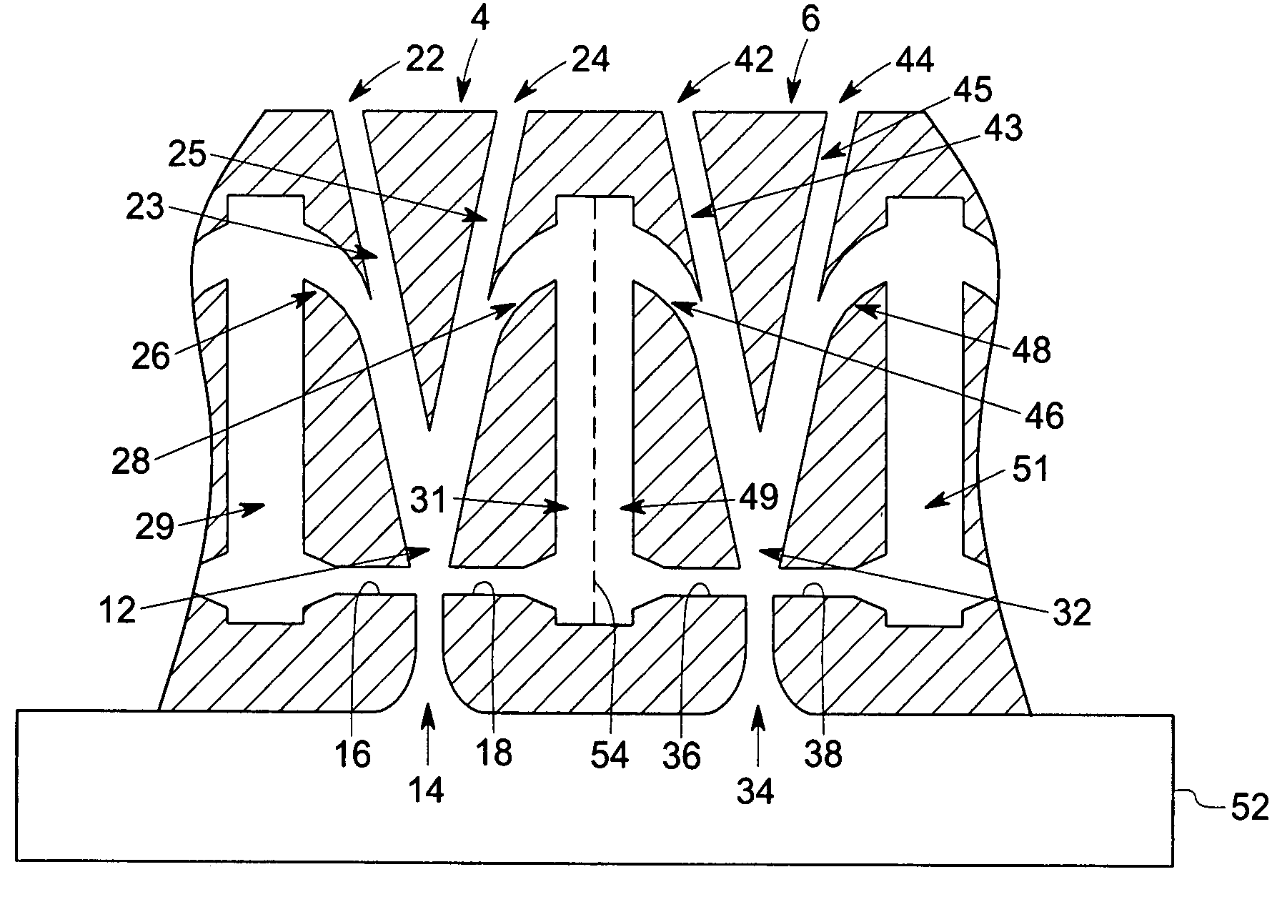
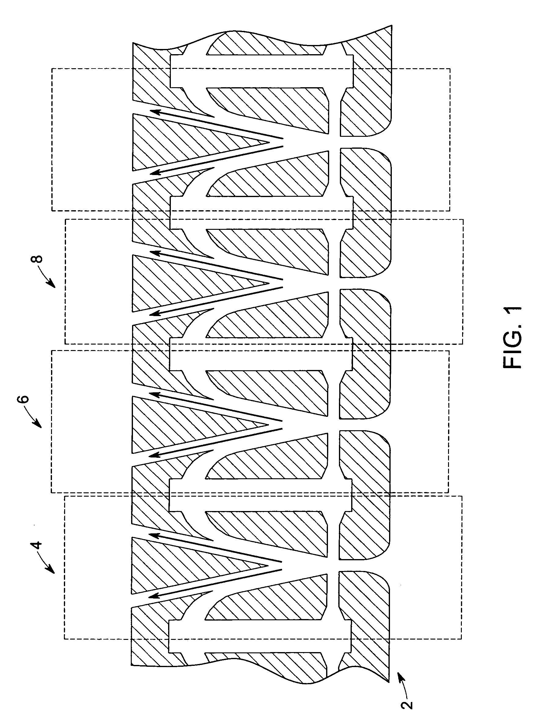
[0010]FIG. 1 is diagrammatical view of an array 2 of fluidic oscillators positioned in a gas turbine engine in accordance with an exemplary embodiment of this invention. The cross section of the array 2 of fluidic oscillators is taken along the axis of the gas turbine engine. The array of fluidic oscillators 2 includes an exemplary first fluidic oscillator 4, an exemplary second fluidic oscillator 6, an exemplary third fluidic oscillator 8 and so on. Details of two exemplary oscillators 4 and 6 are illustrated in FIG. 2.

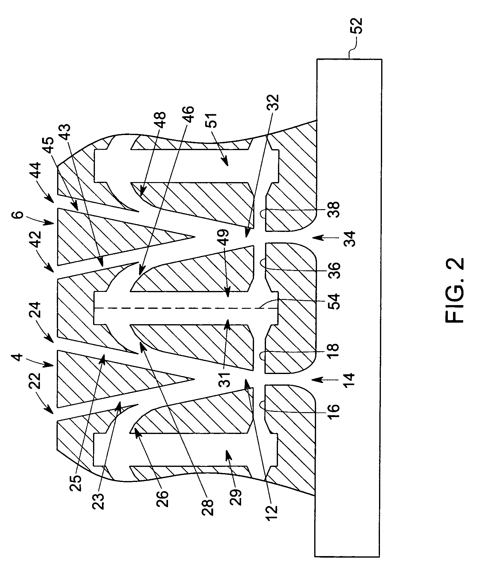
[0011]FIG. 2 is a diagrammatical view of an exemplary first fluidic oscillator 4 and an exemplary second fluidic oscillator 6 positioned in a gas turbine engine in accordance with an exemplary embodiment of this invention. The gas turbine engine carries a flow of a main fluid and the first fluidic oscillator 4 and the second fluidic oscillator 6 each carry a flow of a control fluid. The first fluidic oscillator 4 includes a first throat 12, and a first input port 14,...


PUM


Abstract

A system for control of a fluid flow. The system includes an array of fluidic oscillators. Each fluidic oscillator carries an oscillating flow of the fluid and includes a throat, an input port connected to the throat, two control ports connected to the throat and two output ports extending from the throat. A feedback line is connected to each of the two output ports and each of the two control ports. The system further includes a plenum connected to the input ports of the fluidic oscillators to supply the fluid to the fluidic oscillators and a feedback chamber disposed along each feedback line of each fluidic oscillator to provide a feedback path for the control fluid to cause oscillatory fluid motion between the first output port and the second output port, the frequency of which may be modulated by adjusting the volume of the feedback chamber.

Description

BACKGROUND[0001]Steady boundary layer blowing as a means to remove loss generating separated flow in gas turbine engines is well established. The source of the blowing flow comes from higher pressure regions of the engine or an auxiliary source. The extraction of this high-pressure flow results in a penalty on overall engine performance and efficiency. Prior art on control of boundary layer separation typically reports that the use of unsteady blowing reduces the necessary amount of mass required by steady blowing by factors ranging from 2 to about 100. A means of improving blowing efficiency is to introduce unsteady blowing through fluidic oscillators where a flow of fluid is pulsed without mechanical actuators into the boundary layer upstream of the separation point. However, the frequency, amplitude, and phase of the unsteadiness are critical to proper application of unsteady blowing for boundary layer control.[0002]Therefore there is need of a method of implementing unsteady bou...

Claims


Application Information

Patent Timeline
IPC IPC(8): F15C1/08B05B1/08
CPCB05B1/08B05B7/0075F01D5/145F15C1/22F15D1/12Y02T50/673F05D2260/60Y02T50/60Y10T137/0396Y10T137/212Y10T137/2185Y10T137/2224
Inventor CERRETELLI, CIROKIRTLEY, KEVIN RICHARD
Owner GENERAL ELECTRIC CO
Why Eureka
Try Eureka