
Anti-rewet press fabric

a press fabric and fabric technology, applied in the field of anti-rewetting press fabric, can solve the problems of low paper dry content, high rewetting, and decrease in the contact face of the press fabric against the sh

Active Publication Date: 2006-10-31
ALBANY INT CORP
View PDF31 Cites 18 Cited by
  • Summary
  • Abstract
  • Description
  • Claims
  • Application Information

AI Technical Summary

Benefits of technology

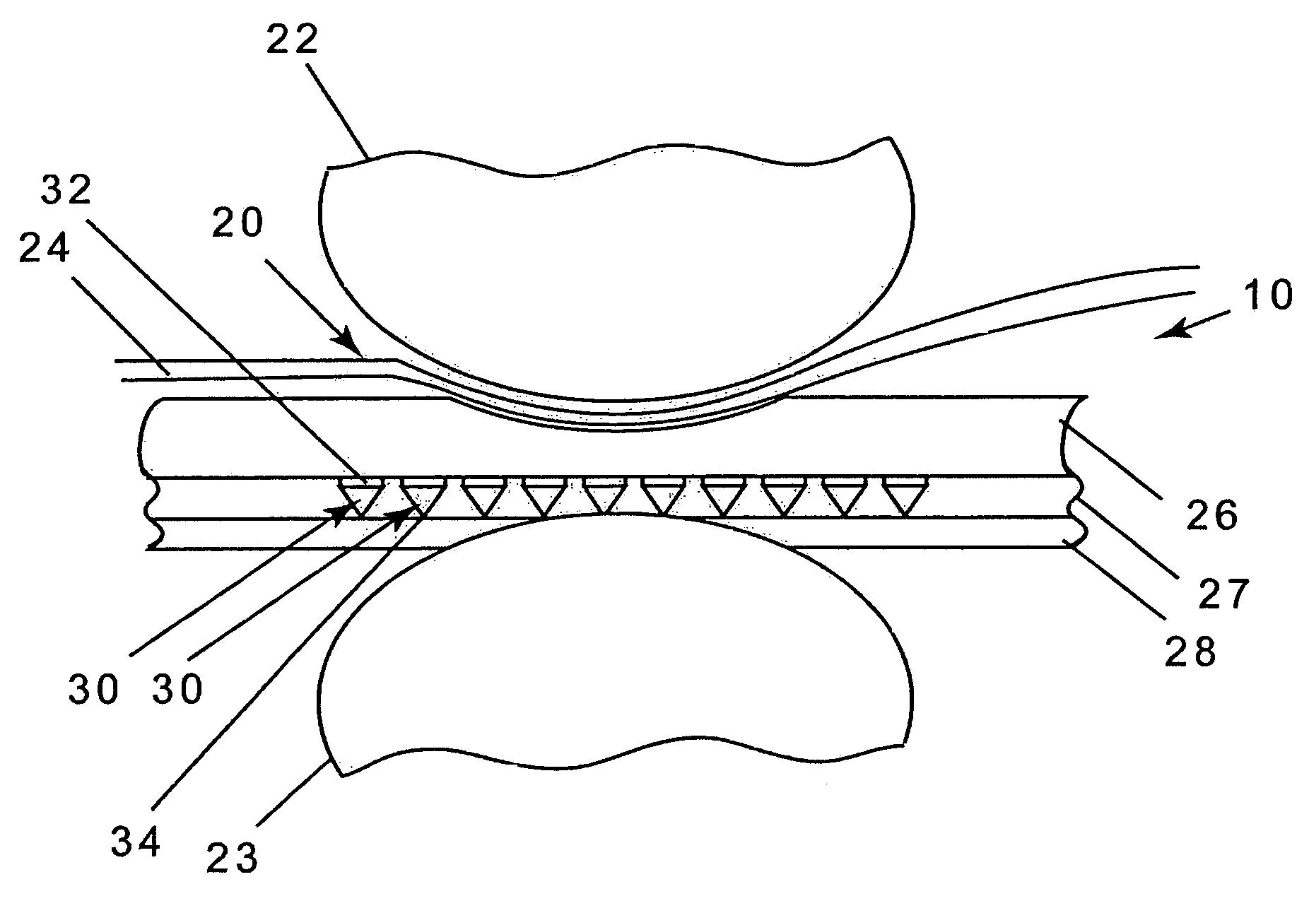
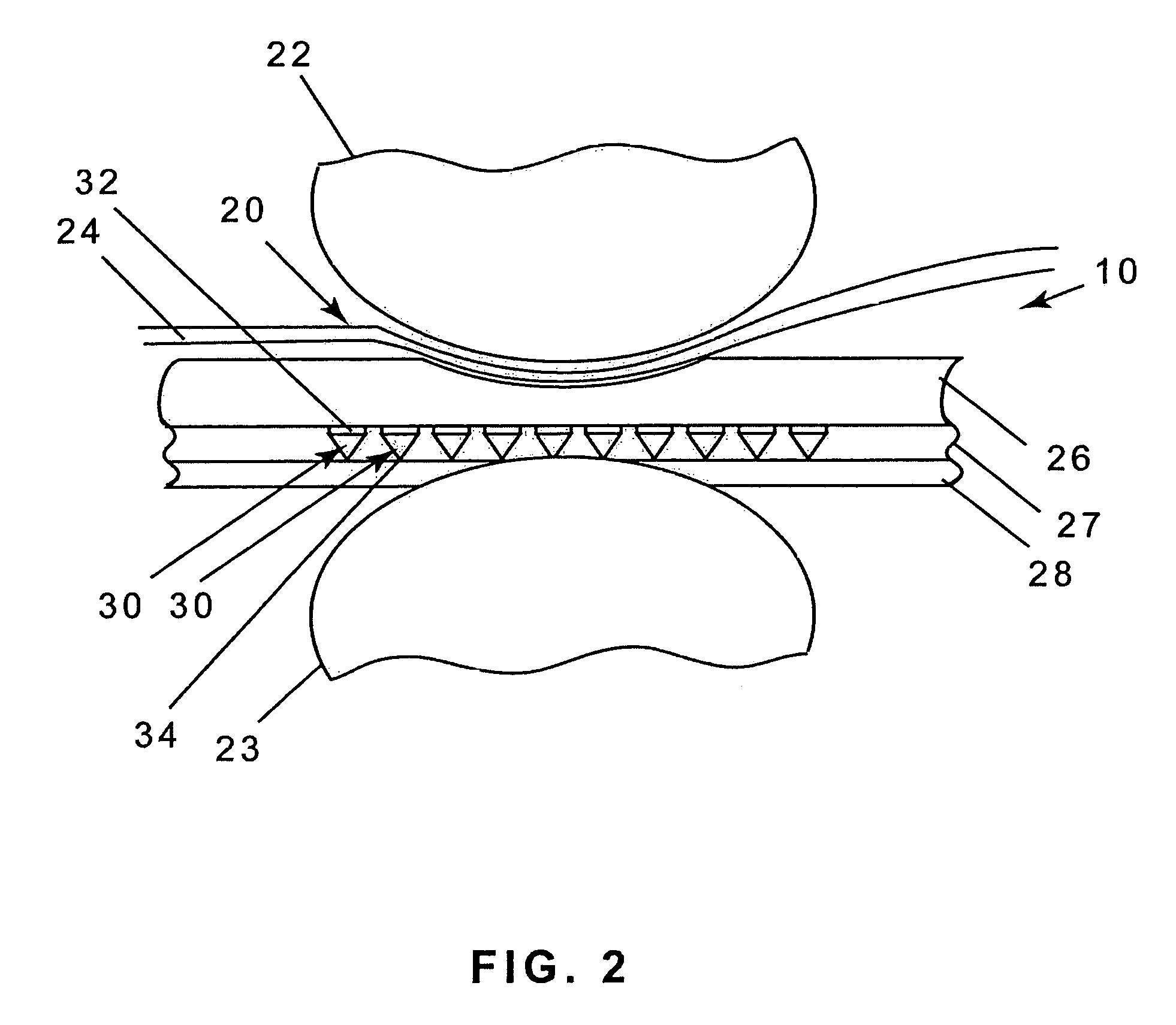
[0028]More specifically, the press fabric of the present invention includes a continuous material possessing, for example, circular, tetrahedral and / or conical inclusions with a smaller opening on the bottom than in the top of the structure. Each of these “funnels” constitutes a one-way valve and creates a vacuum to prevent re-absorption of water by the paper sheet. Under pressure, in the compression zone of the press nip, the structure allows water to flow into the conical structure and out of the smaller opening in the bottom. Upon the release of the pressure in the expansion zone of the nip, the smaller opening in the bottom of the structure restricts backward water flow and creates a vacuum on the other side. The vacuum increases water retention in the press fabric and prevents re-absorption of water into the paper sheet.
[0033]In accordance with one embodiment of the present invention, the barrier layer consists of a polymeric sheet having numerous conical inclusions. These “funnels” in the sheet are so oriented and have a narrow opening in the bottom which allows the water to be let through at the highest pressure during the compression phase but effectively blocks the reverse direction water-flow that is caused by the vacuum during the expansion phase.

Problems solved by technology

When the vacuum of the sheet thus rises considerably during exit from the press nip and the flow resistance in the contact face of the press fabric against the sheet decreases, high rewetting and low paper dry content result.
Needless to say, this requirement makes it difficult to streamline the manufacturing process, as each press fabric must typically be made to order.

Method used


Image

  • Anti-rewet press fabric
  • Anti-rewet press fabric
  • Anti-rewet press fabric

Examples


Embodiment Construction

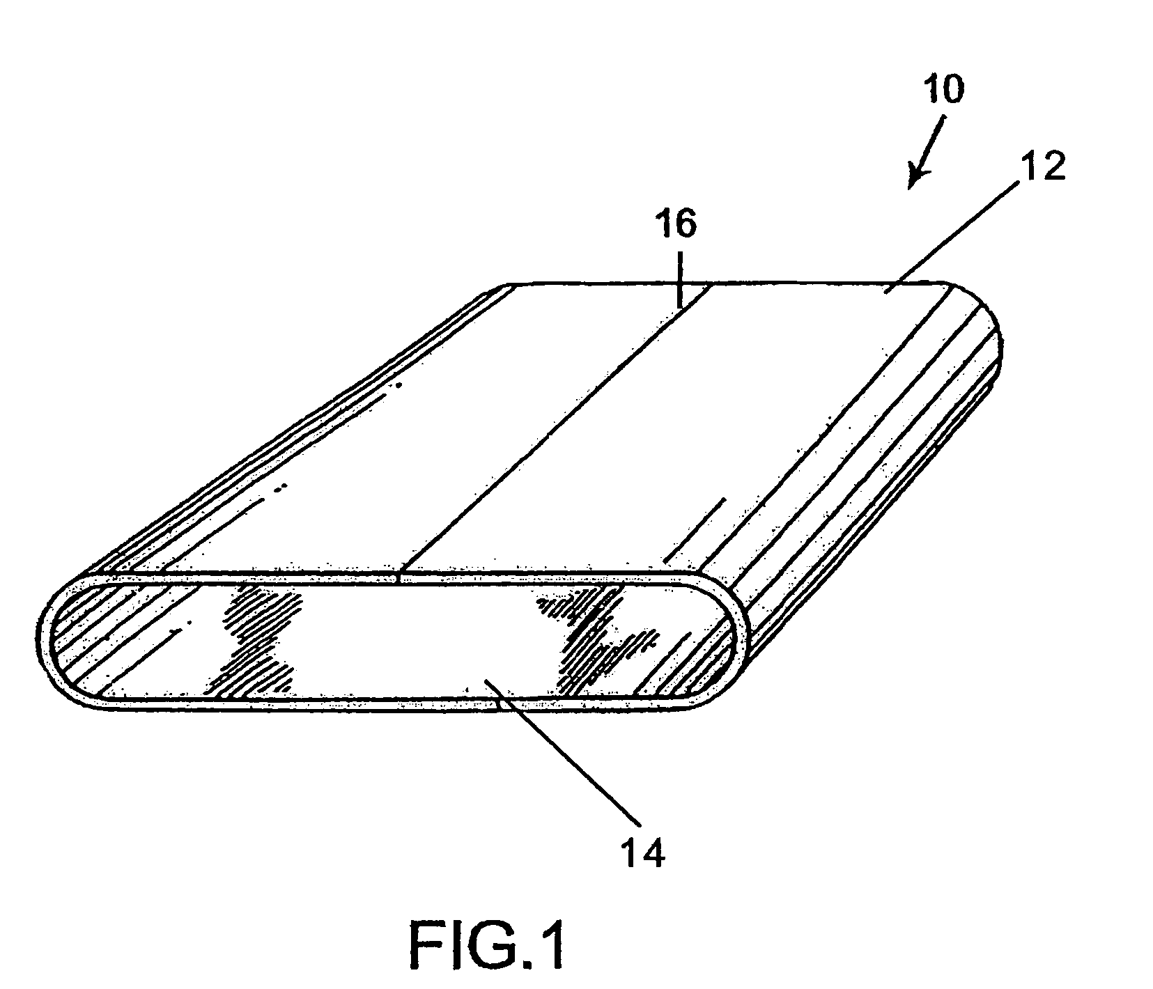
[0040]With reference now to FIG. 1 there is generally shown a press fabric 10 having an inner surface 14 and an outer surface 12. The press fabric 10 shown is an on-machine-seamable type having a seam area 16 which may include a seaming mechanism of the type suitable for the purpose which are well known in the papermaking industry. Of course, the press fabric may also be of the type which is woven endless or spiral formed.

[0041]With reference to FIG. 2, the press nip 20 comprises a top press roll 22 and a bottom press roll 23. The bottom press roll 23 is preferably formed with cavities in the form of suction holes with vacuum, lengthwise extending grooves or blind-drilled holes. A paper web 24 and the press fabric 10 are carried through the press nip 20.

[0042]In its most general form, shown in FIG. 2, the press fabric 10 includes a first, or surface layer 26, attached to a second, or barrier layer 27, and a base support 28 which may be an endless woven base. The surface layer 26 con...


PUM

PropertyMeasurementUnit
flow resistanceaaaaaaaaaa
thicknessaaaaaaaaaa
distanceaaaaaaaaaa

Abstract

An anti-rewet press fabric for paper and board machines includes a barrier layer such that during compression in the press nip, the water is forced through the barrier layer, but is prevented from flowing back to the paper web during expansion. The barrier layer comprises a continuous material possessing, for example square, rectangular, tetrahedral, circular or oblong conical inclusions with a smaller opening on the bottom than on the top of the structure. Each of these “funnels” effectively constitutes a one-way valve and creates a vacuum to prevent re-absorption of water by the paper sheet. Under pressure, the structure of the barrier layer allows water to flow into the cones and out of the smaller opening in the bottom. Upon expansion, the smaller opening in the bottom of the structure restricts backward water flow and creates a vacuum on the other side. The vacuum increases water retention in the press fabric and prevents rewetting of the paper sheet. Another embodiment of the invention is described herein, wherein the barrier layer exists as a separate fabric fed through a press section. In this embodiment, the “separate fabric” can just be the “conical inclusion sheet” itself. That is, the sheet itself constitutes an inventive belt having anti-rewet properties.

Description

BACKGROUND OF THE INVENTION[0001]1. Field of the Invention[0002]The present invention relates to an anti-rewet press fabric with cone-shaped openings for use in the press section of a papermaking machine.[0003]2. Description of the Prior Art[0004]During the papermaking process, a cellulosic fibrous web is formed by depositing a fibrous slurry, that is, an aqueous dispersion of cellulose fibers, onto a moving forming fabric in the forming section of a paper machine. A large amount of water is drained from the slurry through the forming fabric, leaving the cellulosic fibrous web on the surface of the forming fabric.[0005]The newly formed cellulosic fibrous web proceeds from the forming section to a press section, which includes a series of press nips. The cellulosic fibrous web passes through the press nips supported by a press fabric, or, as is often the case, between two such press fabrics. In the press nips, the cellulosic fibrous web is subjected to compressive forces which squeez...

Claims


Application Information

Patent Timeline
Patent Type & Authority Patents(United States)
IPC IPC(8): D21F7/08B32B27/12B32B5/16
CPCD21F7/083Y10T428/24331Y10T428/24273Y10S162/90Y10T442/674Y10T442/662D21F7/08D21F3/00
Inventor HANSEN, ROBERT A.
Owner ALBANY INT CORP
Learn More