Line Driver apparatus

a driver and line technology, applied in the field of electric circuits, can solve the problems of inefficiency, excessive power consumption, and the possibility of data signal clipping, and achieve the effect of preventing signal clipping, reducing disadvantages and problems, and eliminating or greatly reducing disadvantages

Active Publication Date: 2006-10-31
TEXAS INSTR INC
View PDF6 Cites 11 Cited by
  • Summary
  • Abstract
  • Description
  • Claims
  • Application Information

AI Technical Summary

Benefits of technology

[0008]From the foregoing, it may be appreciated by those skilled in the art that a need has arisen for a power efficient system for preventing signal clipping. In accordance with the present invention, a line driver apparatus is provided that substantially eliminates or greatly reduces disadvantages and problems associated with prior signal amplifier systems.

Problems solved by technology

However, the large voltage level is still high enough to lead to excessive power consumption, because much of the time the line driver will not be amplifying a signal requiring the large voltage level.
While prior art zero overhead Class G amplifiers generally provide improved performance, their performance still involves the possibility of clipping the data signal (because the low operating voltage sub-amplifier is used when the incoming signal is above the threshold) or consuming excessive power (because the high operating voltage sub-amplifier is used when the incoming signal is below the threshold).
These inefficiencies can arise because of an inherent inaccuracy in making the threshold determination after the incoming signal has been converted to analog domain and also from the fact that the signal may be distorted by analog filters subsequent to the threshold determination.
As the various sinusoidal signals are delayed, they may constructively or destructively interfere, yielding an output signal different from the input signal.
Constructive interference may cause the zero-overhead amplifier to clip a data signal, as the sub-amplifier was configured for signal data with a lower amplitude.
Alternatively, destructive interference may cause the zero-overhead amplifier to waste power, as the sub-amplifier may be needlessly coupled to a rail to accommodate a now-attenuated data signal.
These and other problems lead to difficulties in determining the correct triggering threshold for the peak detector circuit when making the determination of the triggering threshold in the digital domain.

Method used


Image

  • Line Driver apparatus
  • Line Driver apparatus
  • Line Driver apparatus

Examples


Embodiment Construction

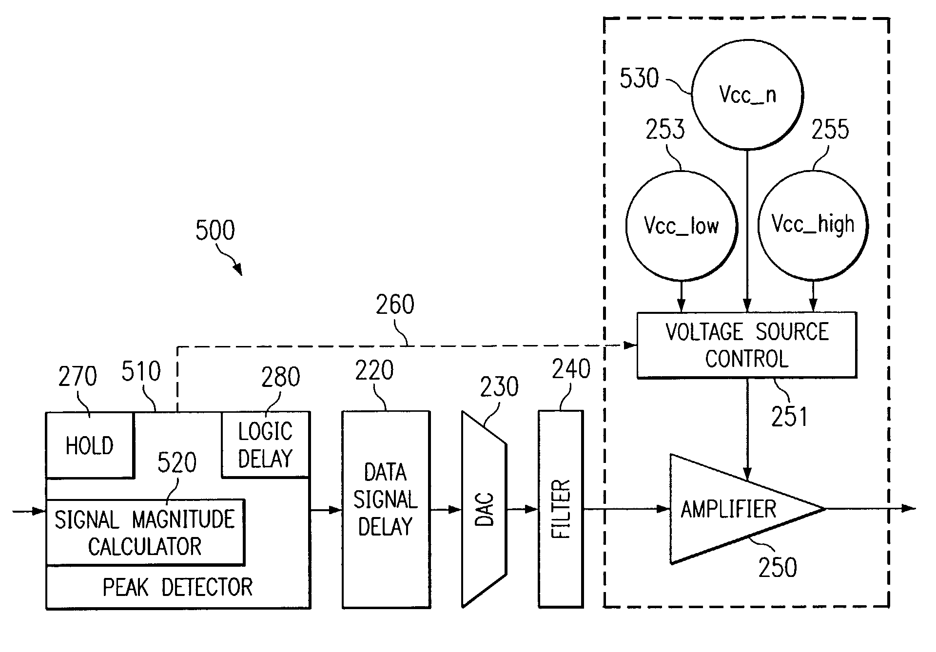
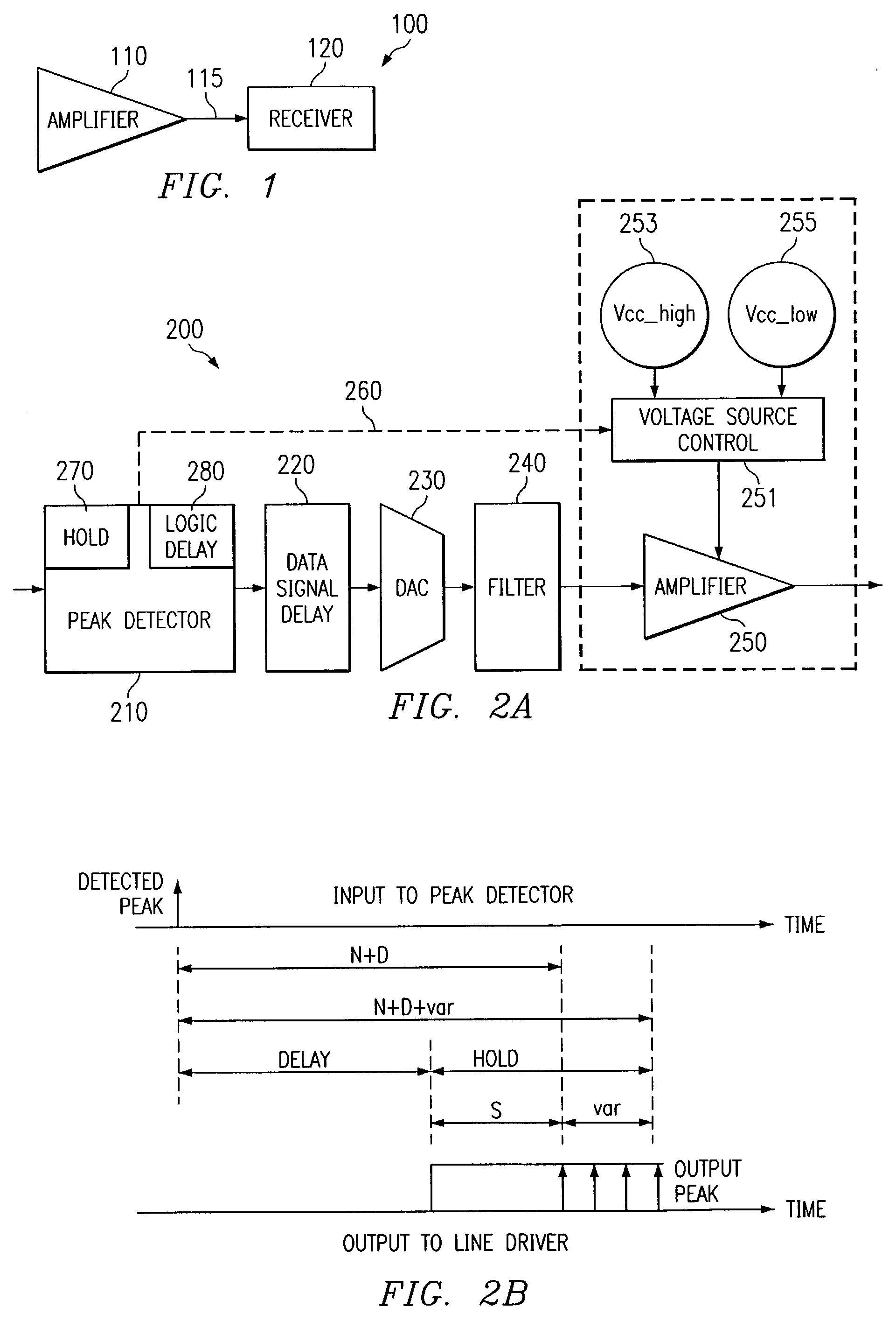
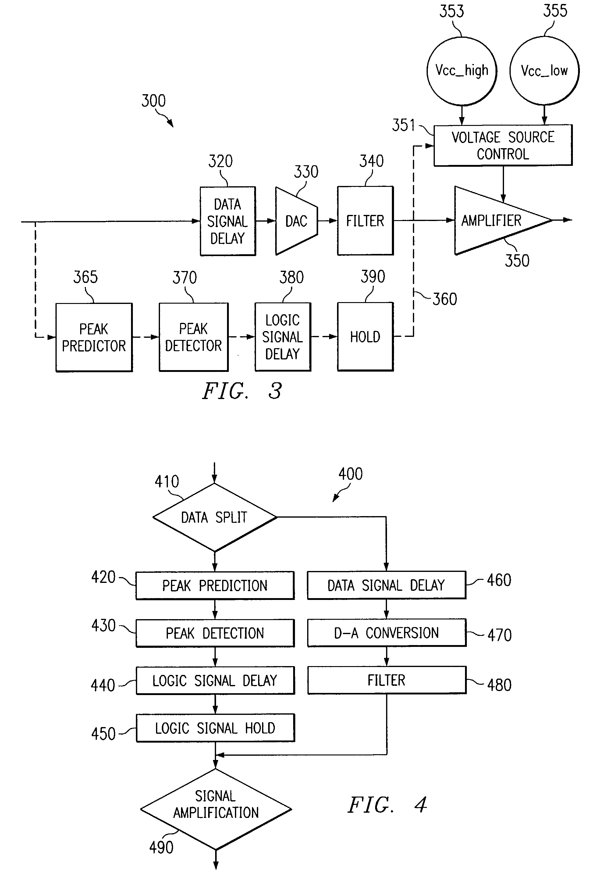
[0019]Details regarding one embodiment of a “zero-overhead” Class G amplifier (“zero-overhead line driver”) are provided in a related application titled “Zero-Overhead Class G Line Driver with Threshold Detection”, Ser. No. 10 / 001,330 and filed on Nov. 11, 2001, which is hereby incorporated by reference in its entirety. By “zero overhead,” it is meant that the amount of pad or tolerance that must be built into the threshold value (in order to ensure the incoming signal is not clipped and that the amplifier does not consume excess power) is minimized by setting the threshold as closely as possible to the theoretical threshold (disregarding measurement inaccuracies, filter distortion, and the like). A zero overhead Class G line driver makes the threshold determination on the incoming signal while the signal is still in the digital domain, thus improving the accuracy of the determination. Additionally, rather than switch between a first or second sub-amplifier, in one embodiment the ze...


PUM


Abstract

A line driver apparatus includes a peak detector operable to receive a data signal and output a first logic signal when the data signal is below a threshold value and output one of a plurality of alternate logic signals when the data signal exceeds the threshold value. The peak detector includes a signal magnitude calculator operable to calculate an amount by which the data signal exceeds the threshold value. The line driver apparatus also includes an amplifier operable to receive a filtered analog data signal and one of a time-delayed first logic signal and one of a time-delayed alternate logic signal, wherein the amplifier operates at a first voltage level upon receiving the time-delayed first logic signal, and the amplifier operates at a voltage level that is increasing toward one of an alternate voltage level upon receiving the time-delayed second logic signal.

Description

RELATED APPLICATIONS[0001]The present application is related to U.S. application Ser. No. 09 / 997,527 entitled “A Programmable Peak Detector for Use with Zero-Overhead Class G Line Drivers” (Attorney Docket No. TI-33111).TECHNICAL FIELD OF THE INVENTION[0002]This invention relates generally to electronic circuits, and more specifically to a line driver apparatus.BACKGROUND OF THE INVENTION[0003]The amplification and line driving of data signals for transmission, such as for use in digital subscriber lines (DSL), constitutes an important link in the transmission of data signals. The transmitted data signals will probably have a substantially Gaussian distribution: a given percentage of symbols constituting the data signals will have an amplitude below a certain amount, and the rest will have an amplitude above that certain amount. When amplifying these symbols for transmission by a line driver, one has typically set the power supply rail of the line driver amplifier at a large voltage...

Claims


Application Information

Patent Timeline
Patent Type & Authority Patents(United States)
IPC IPC(8): H04M19/00H04M1/60
CPCH04M1/6008H04M19/001
Inventor MELSA, PETER J.STETSON, P. SEAN
Owner TEXAS INSTR INC
Why Eureka
Try Eureka