Safety shutdown system for a WDM fiber optic communications network

a fiber optic communications network and safety shutdown technology, applied in the field of fiber optic wdm communications networks, can solve the problems of reducing the reliability requirements of safety shutdown, limiting or failing to detect the loss or absence of the correct signal of the receive signal detector, and the type of receive signal detector failing to properly detect the loss or absence of the correct signal, etc., to achieve the effect of reducing the failure probability factor, reducing the failure rate and eliminating the failure probability factor

Inactive Publication Date: 2006-10-31
WSOU INVESTMENTS LLC
View PDF13 Cites 9 Cited by
  • Summary
  • Abstract
  • Description
  • Claims
  • Application Information

AI Technical Summary

Benefits of technology

[0010]In accordance with the present invention, a method is used for preventing the above-identified detection problems. Also in accordance with this invention a method for performing this more sophisticated detection with reduced failure rate, so that this technique can operate within the reliability limits for safety shutdown is provided. The receive signal detector is designed to declare loss of received signal by detecting the proper signal clock frequency and/or TDM frame pattern. This more sophisticated loss detection method may also include a detector for recognizing the pre-assigned unique signal trace code that is carried in each signal channel's overhead data. However, this more sophisticated detection method for detecting a

Problems solved by technology

A potential limitation or failure of a receive signal detector to detect loss or absence of the correct signal can be due to signal quality problems, such as, for example, increased noise levels and/or adjacent channel cross-talk in a dense WDM system.
In bidirectional WDM transmission systems, reflections caused by broken fibers or dirty connectors can also result in some types of receive signal d

Method used


Image

  • Safety shutdown system for a WDM fiber optic communications network
  • Safety shutdown system for a WDM fiber optic communications network
  • Safety shutdown system for a WDM fiber optic communications network

Examples


Embodiment Construction

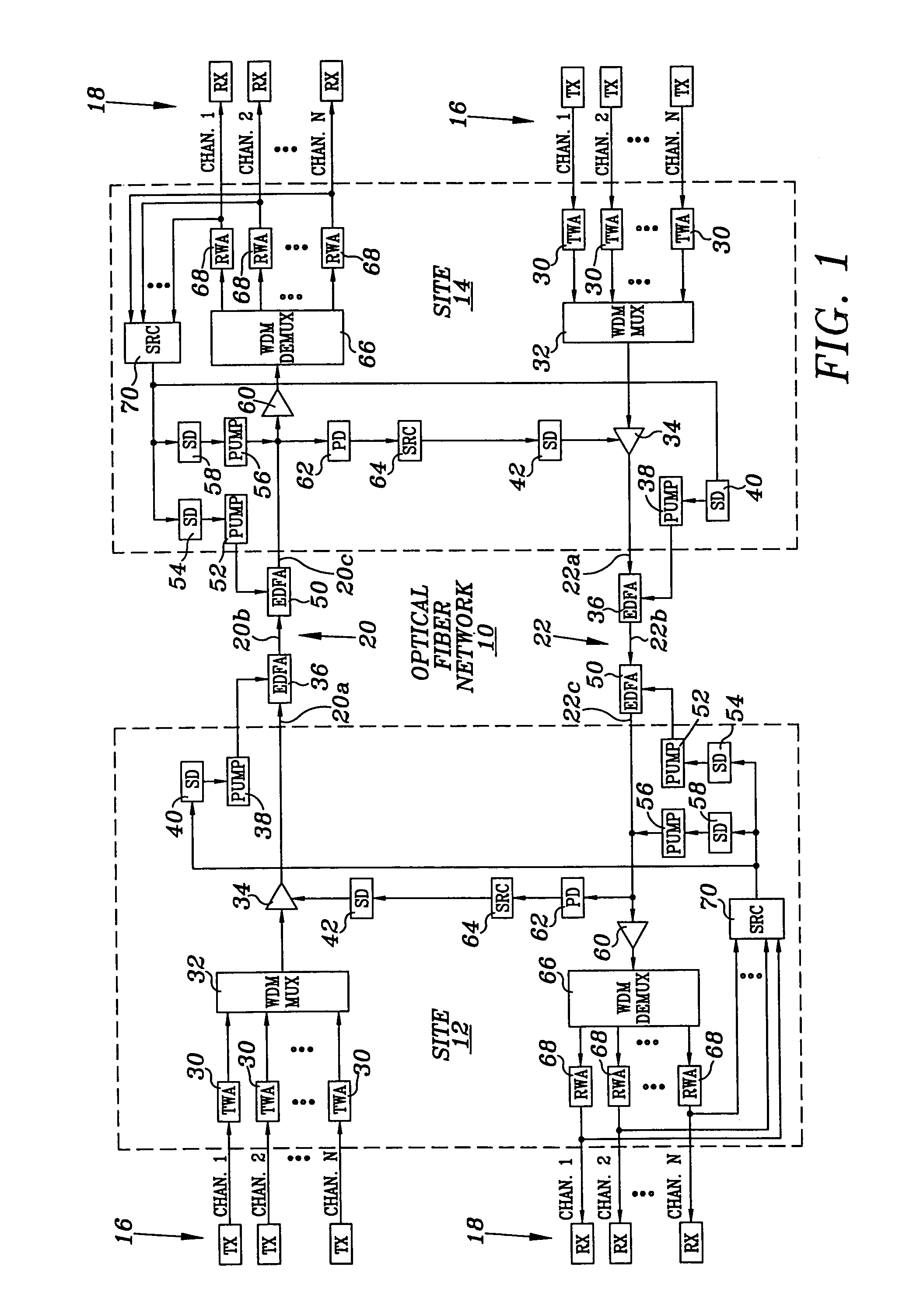
[0014]Referring to FIG. 1, an optical fiber transmission communications network is illustrated, and is generally identified by the numeral 10. Optical fiber transmission network 10 interconnects a site 12 to a site 14. Each site 12 and 14 includes a group of transmitters 16 and a group of receivers 18. Transmitters 16 of site 12 communicate with receivers 18 of site 14 via an optical fiber transmission line, generally identified by the numeral 20. Transmitters 16 of site 14 communicate with receivers 18 of site 12 via an optical fiber transmission line, generally identified by the numeral 22. Whereas network 10 has been illustrated utilizing two lines 20 and 22, the present invention can also be utilized in a bi-directional fiber transmission system.

[0015]Transmitters 16 located at sites 12 and 14 are similarly configured, and like numerals will be utilized for like and corresponding components. Similarly, receivers 18 located at sites 12 and 14 are similarly configured, and like nu...


PUM


Abstract

A fiber optic communications network includes multiple transmitters and multiple receivers connected by an optical WDM transmission link, the receivers having output channels for providing signals to terminal devices, each receiver including a demodulator to detect and recover a received signal, and the network includes at least one optical amplifier having a shutdown input for actuating the safety shut down of the network upon detecting a disconnect in the transmission line. The system includes circuitry connected to the output of each of the demodulators for sensing the presence of a valid signal and for determining whether a predetermined number of valid signals are present at the demodulators. If the number of valid signals detected is less than the predetermined majority number, the safety shutdown function is actuated.

Description

TECHNICAL FIELD OF THE INVENTION[0001]The present invention relates to fiber optic WDM communications networks, and more particularly to a system and method for reliably activating a safety shutdown function in the event of a fiber optic transmission line disconnect or cut.BACKGROUND OF THE INVENTION[0002]The demand for communications capacity on fiber optic communications networks has resulted in increased use of wavelength-division multiplex (WDM) systems. WDM systems provide another level of multiplexing to individual or already multiplexed channels. In WDM systems, the individual transmission channels are carried on separate optical wavelengths and are combined in a single fiber at the optical link layer. WDM systems are generally used when the number of fibers in a transmission link is inadequate for the capacity or becomes a critical cost item.[0003]The distances between WDM optical equipment and the signal transmission rates may be attenuation and / or dispersion limited. As a ...

Claims


Application Information

Patent Timeline
IPC IPC(8): H04B10/08H04B10/17
CPCH04B10/077H04B10/07955H04B10/291
Inventor MAXHAM, KENNETH Y.
Owner WSOU INVESTMENTS LLC
Why Eureka
Try Eureka