Power supply control system and storage device for holding data just prior to the occurence of an error

a power supply control system and data storage technology, applied in the direction of electric variable regulation, process and machine control, instruments, etc., can solve the problems of power supply control lsi, power supply sequence circuits constituted by discrete components, and difficulty in fault analysis of power supply circuit sections

Active Publication Date: 2006-10-31
RAKUTEN GRP INC
View PDF17 Cites 23 Cited by
  • Summary
  • Abstract
  • Description
  • Claims
  • Application Information

AI Technical Summary

Problems solved by technology

In view of this technological background, power supply sequence circuits which are conventionally constituted by discrete components are becoming increasingly complex in structure, in order to respond to the various demands brought by miniaturization of the LSI manufacturing process as described above.
However, the aforementioned power supply control LSI is only provided with a function for performing simple sequence control, and although no problem will arise when the power supply circuit section subject to control is operating in a normal state, if the power supply circuit section declines into an error state, for some reason or other, then the voltage value immediately prior to entering this error state is unknown, and therefore, it is difficult to carry out fault analysis of the power supply circuit section by means of the power supply control LSI described above.
Furthermore, in a storage system comprising a disk array unit constituted by a plurality of storage devices arranged in an array configuration, such as a RAID (Redundant Array of Independent Inexpensive Disks), for example, the process for halting the drive power is complex and varied depending on the type of incident occurring in the system, and hence more detailed control is required and a power supply control LSI such as that described above is not capable of providing a suitable response.

Method used


Image

  • Power supply control system and storage device for holding data just prior to the occurence of an error
  • Power supply control system and storage device for holding data just prior to the occurence of an error
  • Power supply control system and storage device for holding data just prior to the occurence of an error

Examples


first embodiment

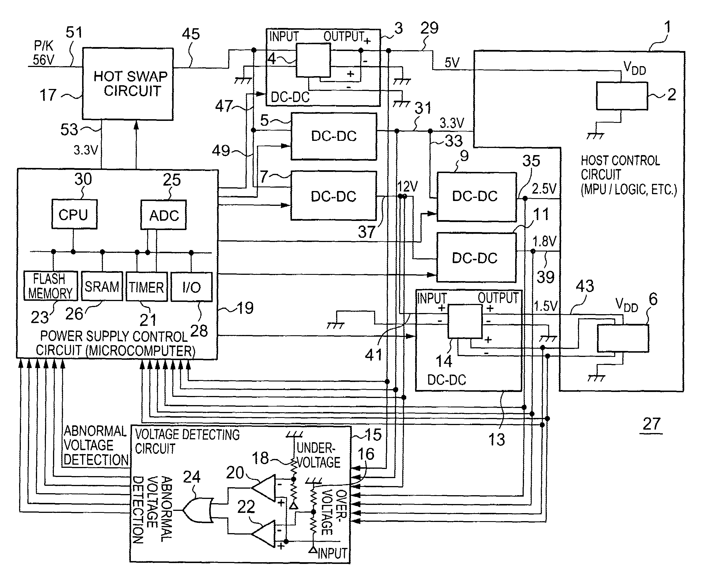
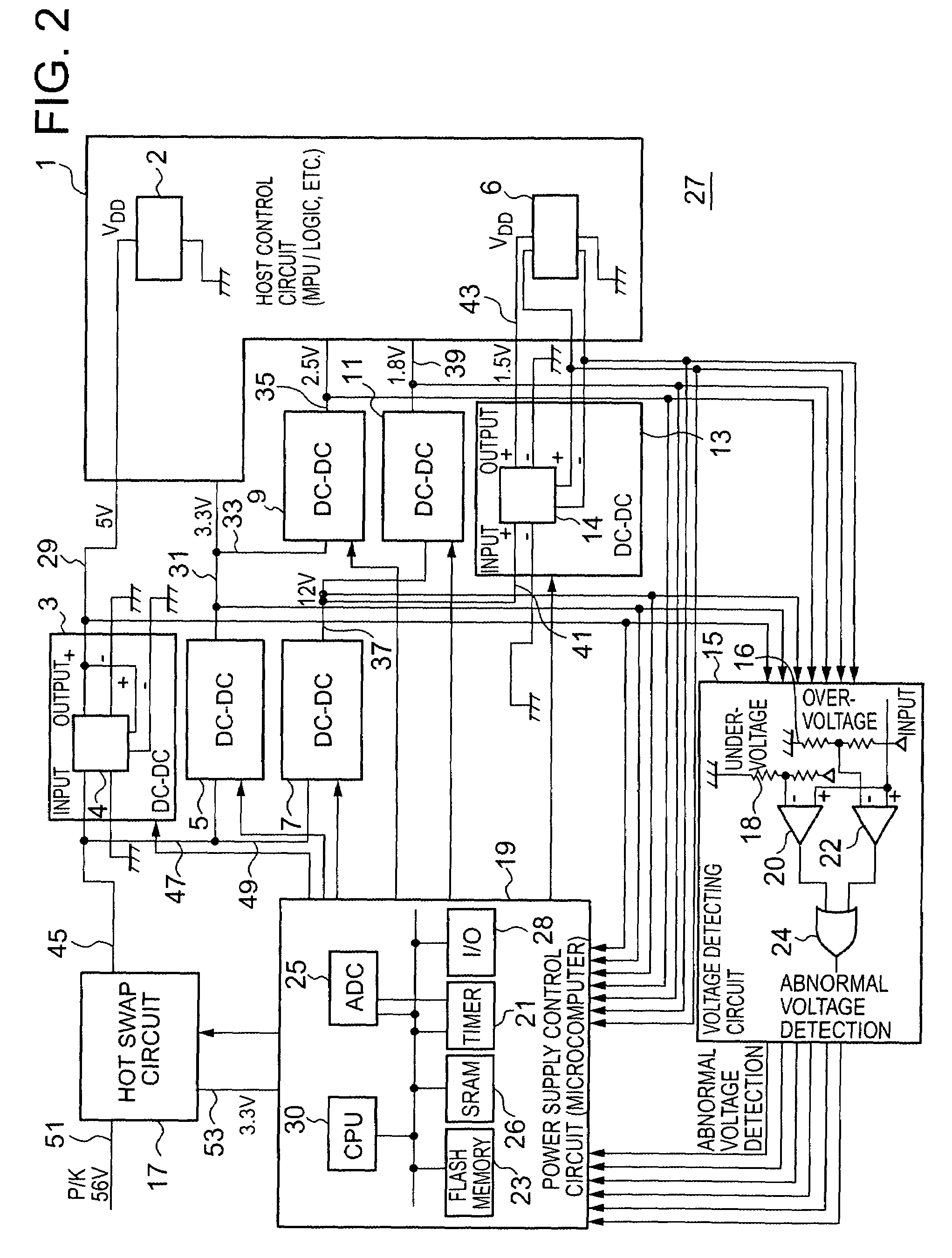
[0056]FIG. 2 is a block diagram showing the general composition of a power supply control system relating to the present invention.

[0057]The aforementioned power supply control system is applied principally in order to control the drive voltage supplied from a power source to a load, such as a host control circuit (1) as described hereinafter, for example, and as illustrated in FIG. 2, this power supply control system is constituted by a host control circuit 1, a plurality of DC / DC converter modules (3, 5, 7, 9, 11, 13), a voltage detecting circuit 15, a hot-swap circuit 17, and a power supply control circuit 19, these elements being mounted on a circuit board 27.

[0058]The host control circuit 1 comprises, for example, a large-scaled integrated circuit (LSI) having a plurality of LSI chips (in FIG. 2, in order to simplify the illustration, only two LSI chips are depicted, respectively labeled with numerals 2 and 6), which function as micro processing units (MPU) or logical computing...

second embodiment

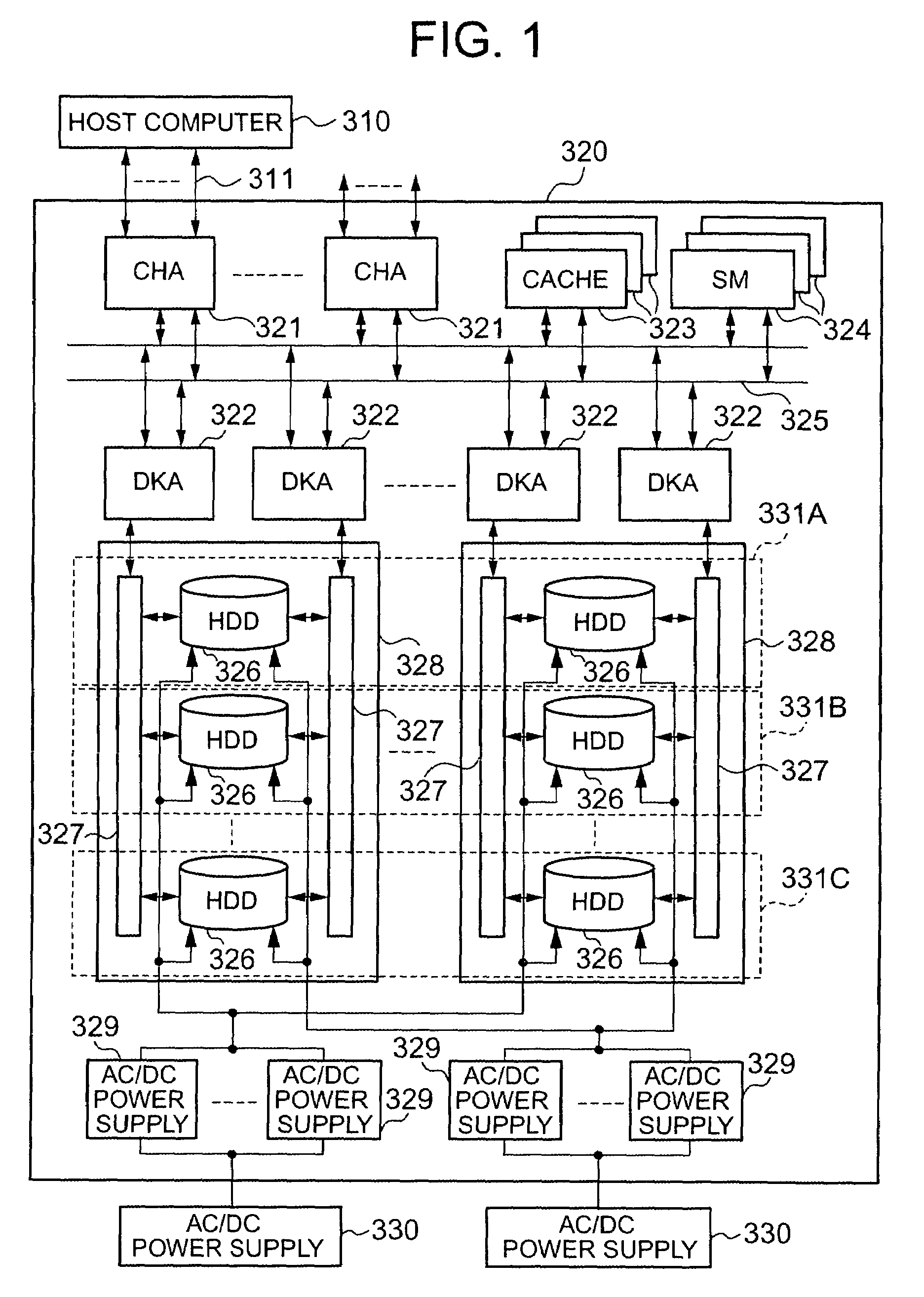
[0118]FIG. 12 is a block diagram showing the general composition of a storage system relating to the present invention. As shown in FIG. 12, this storage system comprises two storage control devices, 171, 173 having the same internal composition.

[0119]In FIG. 12, the storage control device 171 comprises a plurality of channel adapters (CHA) (only the CHA labeled 175 is illustrated in FIG. 12), a cache memory (CACHE) 177, a switching control section (CSW) 179, a shared memory (SM) 181, a plurality of disk adapters (DKA) (only the DKA labeled 183 is illustrated in FIG. 12), and a plurality of storage devices 185, 187, 189, 191. If the commercial power source (AC 200V) is in a normal state, then DC power at the prescribed voltage (for example, 56V) is supplied respectively as a drive voltage, to each of the aforementioned sections, by the AC / DC converter 193. However, if the commercial power source (AC 200V) has been interrupted, then drive power is only supplied from the back-up power...


PUM


Abstract

A computing section controls a hot swap circuit, and DC / DC converters based on binary data from an ADC and an interrupt signal from respective comparing sections of a voltage detecting circuit. If the interrupt signal is input from any one of the respective comparing sections, the reading of binary data corresponding to the interrupt signal is halted. The binary data relating to the voltage detecting section corresponding to the interrupt signal, which is held in the SRAM at that time, is transferred to a non-volatile memory, where it is stored. When driving of the system has been halted, binary data is read out from the non-volatile memory, in order to analyze the cause of the error in a DC / DC converter which indicates an error output voltage from one of power supply circuits for supplying externally a plurality of different drive voltages to loads in a disk array unit.

Description

CROSS-REFERENCE TO PRIOR APPLICATION[0001]This application relates to and claims priority from Japanese Patent Application Nos. 2004-113829, filed on Apr. 8, 2004 the entire disclosure of which are incorporated herein by reference.BACKGROUND OF THE INVENTION[0002]1. Field of the Invention[0003]The present invention relates to a power supply control system comprising a plurality of power supply circuits which supply powers to loads driven at a plurality of voltages, at voltages corresponding respectively to the plurality of voltages, and to a storage device comprising a disk drive unit for storing input data, and a cache memory which temporarily keeps the data stored in the disk drive unit.[0004]2. Description of the Related Art[0005]In the prior art, a power sequence detecting unit has been proposed with the aim of shortening the time required until the cause of an operational fault can be identified, in cases where an operational fault occurs in the power supply section, due to an ...

Claims


Application Information

Patent Timeline
Patent Type & Authority Patents(United States)
IPC IPC(8): G06F1/30H02H9/00G06F1/28G01R31/30G01R31/317G05F1/00G05F1/10G06F1/20G06F1/26G06F3/06G06F11/00G06F11/20
CPCG01R31/3004G01R31/31721G06F1/206G06F1/26G06F11/2015
Inventor SASAKURA, TAKAHIROABE, SEIICHI
Owner RAKUTEN GRP INC
Why Eureka
Try Eureka