
Apparatus and methods for occluding an access tube anastomosed to sidewall of an anatomical vessel

Inactive Publication Date: 2006-11-07
VITAL ACCESS CORP
View PDF81 Cites 28 Cited by
  • Summary
  • Abstract
  • Description
  • Claims
  • Application Information

AI Technical Summary

Benefits of technology

[0013]The present invention provides methods and apparatus for facilitating long-term, repeated vascular access while minimizing the problems typically associated with such devices. By minimizing the surface area of non-native or externally introduced material exposed to blood flow in the vessels, and by making those surfaces that are exposed easily replaceable, many complications can be controlled or eliminated.
[0014]These objects are achieved by providing an access tube apparatus that is adapted for anastomosis to the sidewall of a target blood vessel. After a hole is formed in the sidewall of the target vessel, the access tube can be anastomosed to the vessel using any desired method, including suturing, stapling, clamping, welding, adhesives, etc. In one embodiment, the access tube has an attached or integrally formed anastomosis ring with guide posts fitting within slots in an attached or integrally formed portion of the access tube to facilitate the anastomosis procedure. Once anastomosed to the target vessel sidewall, the access tube apparatus extends through the patient's skin with an access end that is externally accessible.
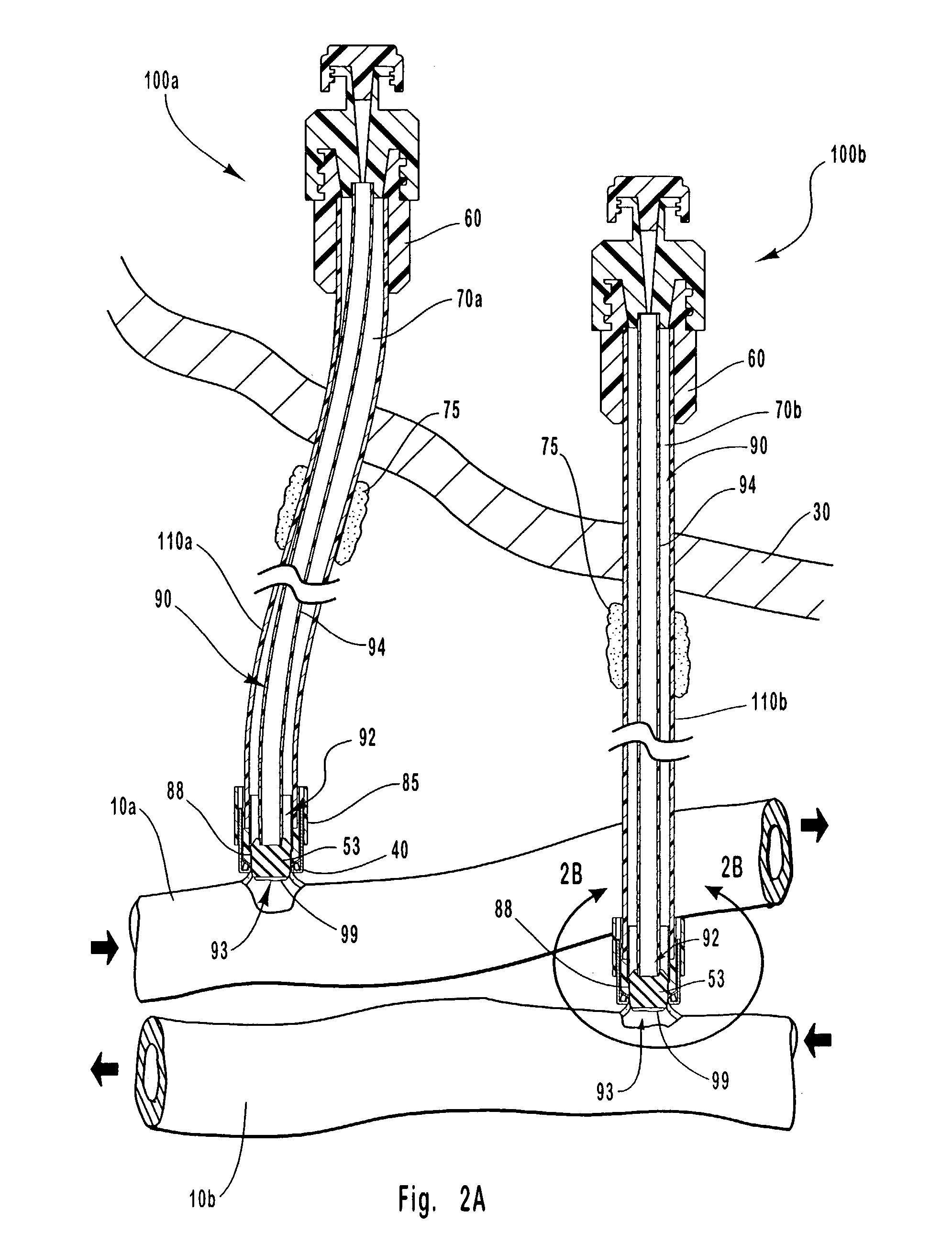
[0015]Fitting within the conduit of the access tube is an occluder. Preferably, the occlusion end of the occluder extends all the way to the target vessel wall without extending significantly into the vessel lumen. In other words, the occlusion end preferably abuts the target vessel wall and is approximately flush with the vessel wall such that the blood has a relatively smooth flow path around the area in which the access tube is attached to the vessel. This helps to minimize complications resulting from blood-flow disturbances.

Problems solved by technology

The multiple punctures that such repeated access necessitates eventually render the accessed vessels unsuitable for further effective injections.
However, there are a number of drawbacks to such catheter systems.
For example, because the catheters of such systems are inserted directly into the lumen of a patient's blood vessel, they obstruct blood flow in the vessels.
Therefore, the diameter of catheters available for dialysis is quite limited.
Because high flow rates through catheters are desirable to maximize the efficiency of dialysis procedures, this limitation is disadvantageous.
For example, because the catheters of such systems are inserted directly into a patient's bloodstream, they are susceptible to developing thrombi, infection, and / or other complications.
These repeated punctures can damage a patient's blood vessels to the extent that they can no longer withstand further punctures.
Also, repeated punctures of a patient's skin can be painful and can likewise damage the skin.
Moreover, because the repeated use of larger needles and catheters causes greater damage to a patient's blood vessels and skin, this further limits the effectiveness of conventional dialysis procedures.
First, in Buselmeier, blood flow in the shunt tube is constantly exposed to foreign or non-native surfaces which are not easily replaceable—i.e., not without further recurring surgical procedures.
Because there is such a large non-native surface area exposed to blood flow in the vessel, and because those surfaces that are exposed are not easily replaceable, the Buselmeier device is prone to complications such as thrombosis, blood stagnation, and infection.
Moreover, the surgeries themselves tend to cause trauma to the vessels being accessed, which may ultimately leave them unsuitable for further access.
For at least these reasons, the Buselmeier configuration is not suitable for effective long-term vascular access.
These fluid flow dissimilarities may lead to additional adverse effects that detrimentally affect the long term accessibility of the blood vessels that must be accessed for the external blood treatment to be effectively performed.
The prior art has yet to provide an apparatus or system having the desirable characteristics discussed above.

Method used


Image

  • Apparatus and methods for occluding an access tube anastomosed to sidewall of an anatomical vessel
  • Apparatus and methods for occluding an access tube anastomosed to sidewall of an anatomical vessel
  • Apparatus and methods for occluding an access tube anastomosed to sidewall of an anatomical vessel

Examples


Embodiment Construction

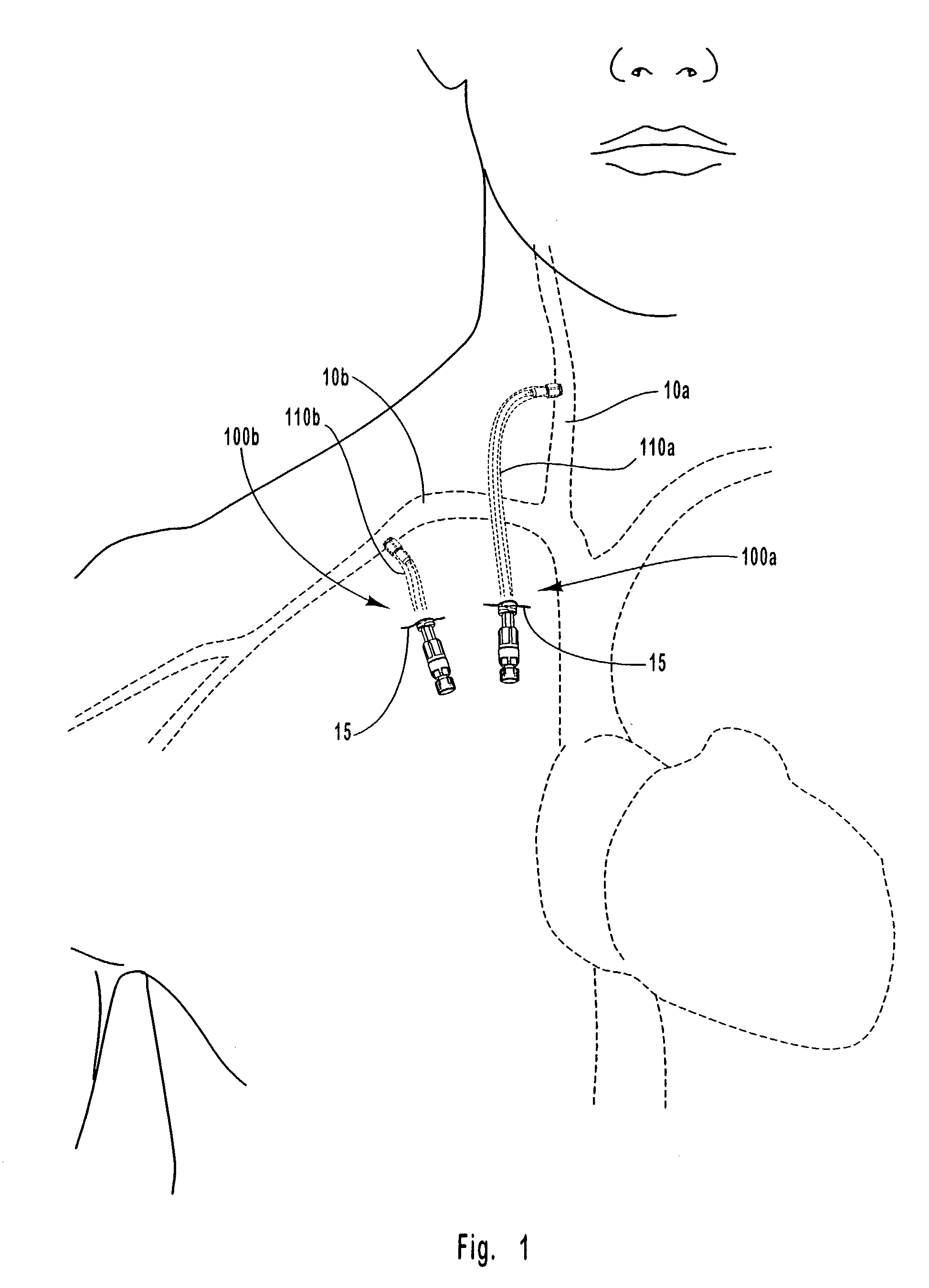
[0048]Several different embodiments of the occludable access tube apparatus are disclosed herein. One embodiment of the apparatus of the present invention is shown in FIGS. 1–4H at 100. Other embodiments are identified as 100′ and 100″ respectively in FIGS. 5 and 6.

[0049]The primary components of the device include the following. First, an access tube is provided, identified generally at 110, which is adapted for anastomosis to an anatomical vessel at an anastomosis end. The anastomosis procedure is typically facilitated by the use of an anastomosis component, identified as a target vessel anastomosis ring 40 in several of the accompanying figures. The target vessel anastomosis ring may be adapted to cooperate with an access tube anastomosis ring, identified generally at 85, in accomplishing the anastomosis procedure.

[0050]An access end of access tube 110 opposite from an anastomosis end extends through the skin and is externally accessible. Fitting within the access tube at the acc...


PUM


Abstract

The invention provides vascular access methods, systems and devices facilitating long-term, repeated, percutaneous access to a patient's blood stream. This is provided by an access tube apparatus adapted for anastomosis to the sidewall of a target anatomical vessel. The access tube has a replaceable occluder that fits within the conduit of the access tube in between blood treatments or when vascular access is otherwise not needed. When such access is desired, the percutaneously accessible occluder is simply removed from the access tube.

Description

TECHNICAL FIELD[0001]The present invention relates to vascular access methods and apparatus. More particularly, it relates to such methods and apparatus that allow for repeated percutaneous access to an anatomical vessel such that repeated punctures of the vessel and / or the patient's skin are not necessary.BACKGROUND OF THE INVENTION[0002]Examples of procedures that require repeated access to anatomical vessels include dialysis and the delivery of medicines for an extended period of time. The multiple punctures that such repeated access necessitates eventually render the accessed vessels unsuitable for further effective injections. Accordingly, there is a need for apparatus, methods, and systems for facilitating long-term, repeated vascular access.[0003]Dialysis procedures, for example, typically employ catheters, which are inserted into a patient's bloodstream to withdraw blood for treatment and then return treated blood back into the bloodstream. However, there are a number of dra...

Claims


Application Information

Patent Timeline
IPC IPC(8): A61M37/00A61B17/08C02F1/44A61B17/11A61B17/32A61B17/34A61M1/36
CPCA61M1/3653A61M1/3661A61B17/32053A61B2017/1135A61B2017/3488A61M1/3655A61M1/3659
Inventor BLATTER, DUANE D.ORR, TROY J.BARRUS, MICHAEL C.
Owner VITAL ACCESS CORP
Learn More