Endoluminal prosthetic assembly and extension method

a prosthetic and endoluminal technology, applied in the field of implantable medical devices, can solve problems such as health risk, gradual vessel expansion, stroke or other vessel blockage,

Inactive Publication Date: 2006-11-07
MEDTRONIC VASCULAR INC
View PDF10 Cites 74 Cited by
  • Summary
  • Abstract
  • Description
  • Claims
  • Application Information

AI Technical Summary

Problems solved by technology

An aneurysm is produced when a thinning or weak spot in a vessel wall dilates eventually posing a health risk from its potential to rupture, clot, or dissect.
Left untreated, AAA may lead to gradual vessel expansion, thrombus formation leading to stroke or other vessel blockage, vessel rupture, shock, and eventual death.
The aneurysm may begin with a small vessel distension that progressively enlarges at a variable and unpredictable rate.
Once reaching about 8 cm, however, there is about a 75 percent chance of rupture within a year.
Besides rupture, another risk of AAA is thrombus dissection.
Pieces of the clot may eventually loosen and carry away, eventually forming blockages in the legs, lungs, or brain.
The surgical procedure is complex and requires experienced surgeons and well equipped surgical facilities.
Even with the best surgeons and equipment, patients suffering from such aneurysms are often elderly and weakened from cardiovascular and other diseases.
Even for eligible patients prior to rupture, conventional aneurysm repair has a relatively high mortality rate, usually from 2 to 10%.
Even with successful surgery, recovery takes several weeks and often requires a lengthy hospital stay.
Failing to do so may result in leakage into the aneurysm.
Multiple extension cuffs used in series may be particularly vulnerable to such stresses due to the presence of multiple joints.
Undetected module separation may lead to continued leakage, aneurysm regrowth, and even the more serious problems associated with AAA.

Method used


Image

  • Endoluminal prosthetic assembly and extension method
  • Endoluminal prosthetic assembly and extension method
  • Endoluminal prosthetic assembly and extension method

Examples


Embodiment Construction

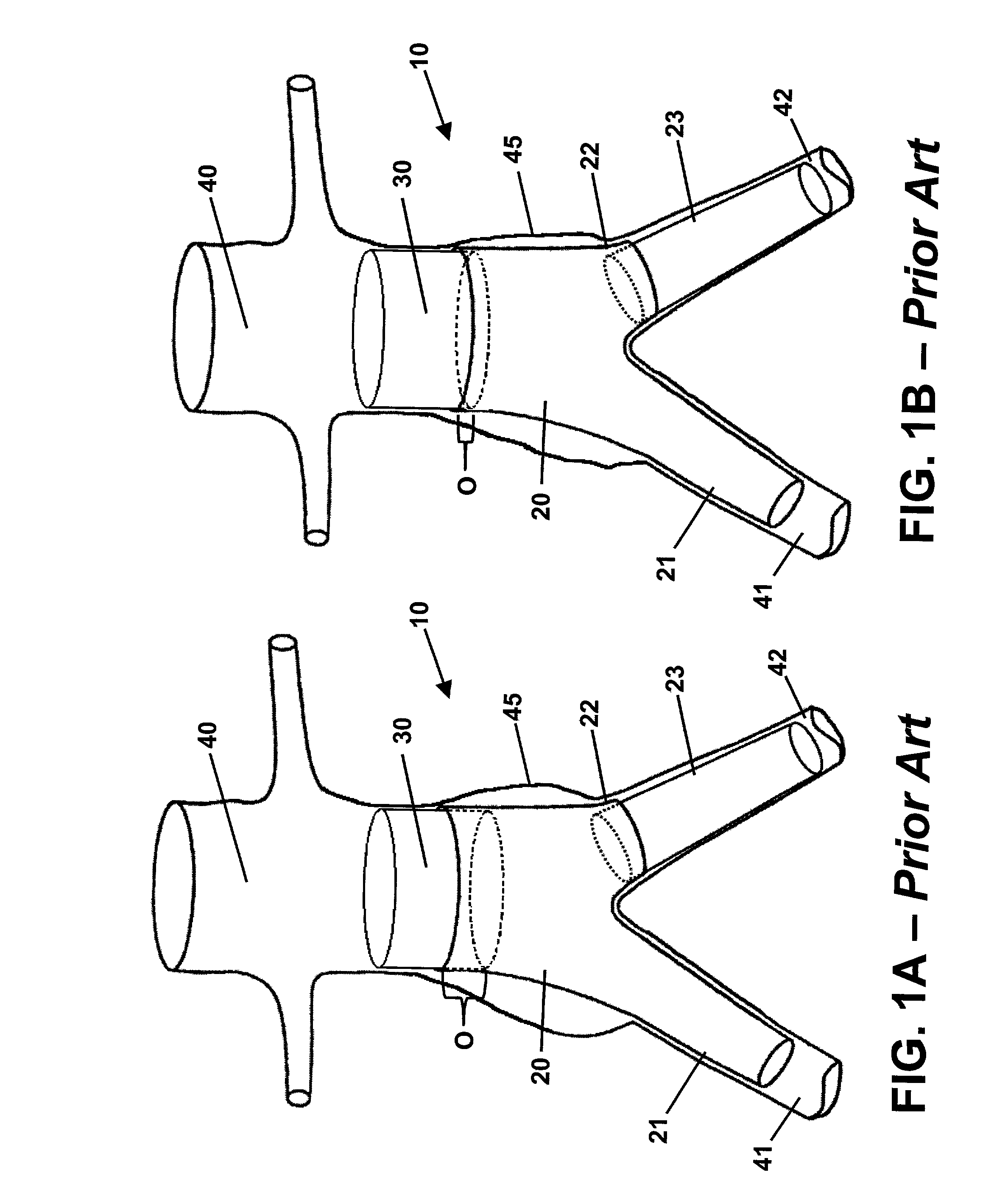
[0019]Referring to the drawings, wherein like reference numerals refer to like elements, FIGS. 1A and 1B are sequential views of a prior art endoluminal prosthetic assembly 10 including extension cuff 30 deployed in an abdominal aortic aneurysm 45. Assembly 10 includes a tubular trunk body 20, a first branch body 21, and a shortened branch body 22. A second branch body 23 is operably attached to the shortened branch body 22. Trunk body 20 includes a relatively large lumen and is deployed in patient abdominal aorta 40. Trunk body 20 lumen bifurcates into smaller branch lumens of the first branch body 21 and second branch body 23. The branch bodies 21, 23 are deployed within first iliac artery 41 and second iliac artery 42. The deployed trunk body 20 and branch bodies 21, 23 preferably seal to each other and to the healthy vascular walls beyond the aneurysm 45 isolating the aneurysm 45 from the bloodstream. As previously described, aortic blood flow that enters the trunk body 20 lumen...


PUM


Abstract

An endoluminal prosthetic assembly includes a trunk body including first and second elongated branches. The trunk body and elongated branches include a bifurcated body lumen formed therein. The assembly further includes an extension cuff including a cuff branch and an access port. The extension cuff, cuff branch, and access port include a bifurcated cuff lumen formed therein. A portion of the extension cuff is retainably positioned within the trunk body. A portion of the cuff branch is retainably positioned within one of the elongated branches. The cuff lumen is in communication with the body lumen. A method of extending an endoluminal prosthetic assembly deployed in a bifurcated vessel is also provided. The assembly includes a trunk body including first and second elongated branches. A portion of a compressed extension cuff is positioned within the trunk body and the first elongated branch. The compressed extension cuff is expanded into operable engagement with the trunk body and the first elongated branch.

Description

TECHNICAL FIELD OF THE INVENTION[0001]The present invention relates generally to the field of implantable medical devices. More particularly, the invention relates to a bifurcated endoluminal prosthetic assembly and a method of extension.BACKGROUND OF THE INVENTION[0002]Abdominal aortic aneurysms (AAA) represent one of the most common types of aneurysms and result in about 15,000 deaths annually in the United States. An aneurysm is produced when a thinning or weak spot in a vessel wall dilates eventually posing a health risk from its potential to rupture, clot, or dissect. An aneurysm frequently occurs in arteries, but may also form in veins. The etiology of aneurysm formation is not entirely understood, but is thought to be related to congenital thinning of the artery, atherosclerotic vessel degeneration, vessel trauma, infection, smoking, high blood pressure, and other causes leading to vessel degeneration. Left untreated, AAA may lead to gradual vessel expansion, thrombus formati...

Claims


Application Information

Patent Timeline
Patent Type & Authority Patents(United States)
IPC IPC(8): A61F2/06
CPCA61F2/07A61F2002/067A61F2002/075A61F2/89A61F2220/0033A61F2220/0091A61F2230/0054
Inventor ZARINS, CHRISTOPHER K.DOIG, SCOTT A.
Owner MEDTRONIC VASCULAR INC
Why Eureka
Try Eureka