PLL with built-in filter-capacitor leakage-tester with current pump and comparator

a filter capacitor and leakage test technology, applied in the field of phaselocked loops (plls), can solve the problems of complex electronic system operation, prone to point defects, and related manufacturing of ic chips

Inactive Publication Date: 2006-11-07
DIODES INC
View PDF23 Cites 68 Cited by
  • Summary
  • Abstract
  • Description
  • Claims
  • Application Information

AI Technical Summary

Problems solved by technology

Many of today's complex electronic systems operate synchronously and require generation of one or more clocks.
The cost of manufacturing such IC chips is related to the manufacturing yield.
Yield is limited because small particles such as dust can land on the surface of the chip during processing, resulting in a point defect.
Other causes of such point defects may include impurities in manufacturing chemicals and materials.
The large area required by capacitor 20 can make it particu...

Method used


Image

  • PLL with built-in filter-capacitor leakage-tester with current pump and comparator
  • PLL with built-in filter-capacitor leakage-tester with current pump and comparator
  • PLL with built-in filter-capacitor leakage-tester with current pump and comparator

Examples


Embodiment Construction

[0016]The present invention relates to an improvement in PLL test circuits. The following description is presented to enable one of ordinary skill in the art to make and use the invention as provided in the context of a particular application and its requirements. Various modifications to the preferred embodiment will be apparent to those with skill in the art, and the general principles defined herein may be applied to other embodiments. Therefore, the present invention is not intended to be limited to the particular embodiments shown and described, but is to be accorded the widest scope consistent with the principles and novel features herein disclosed.

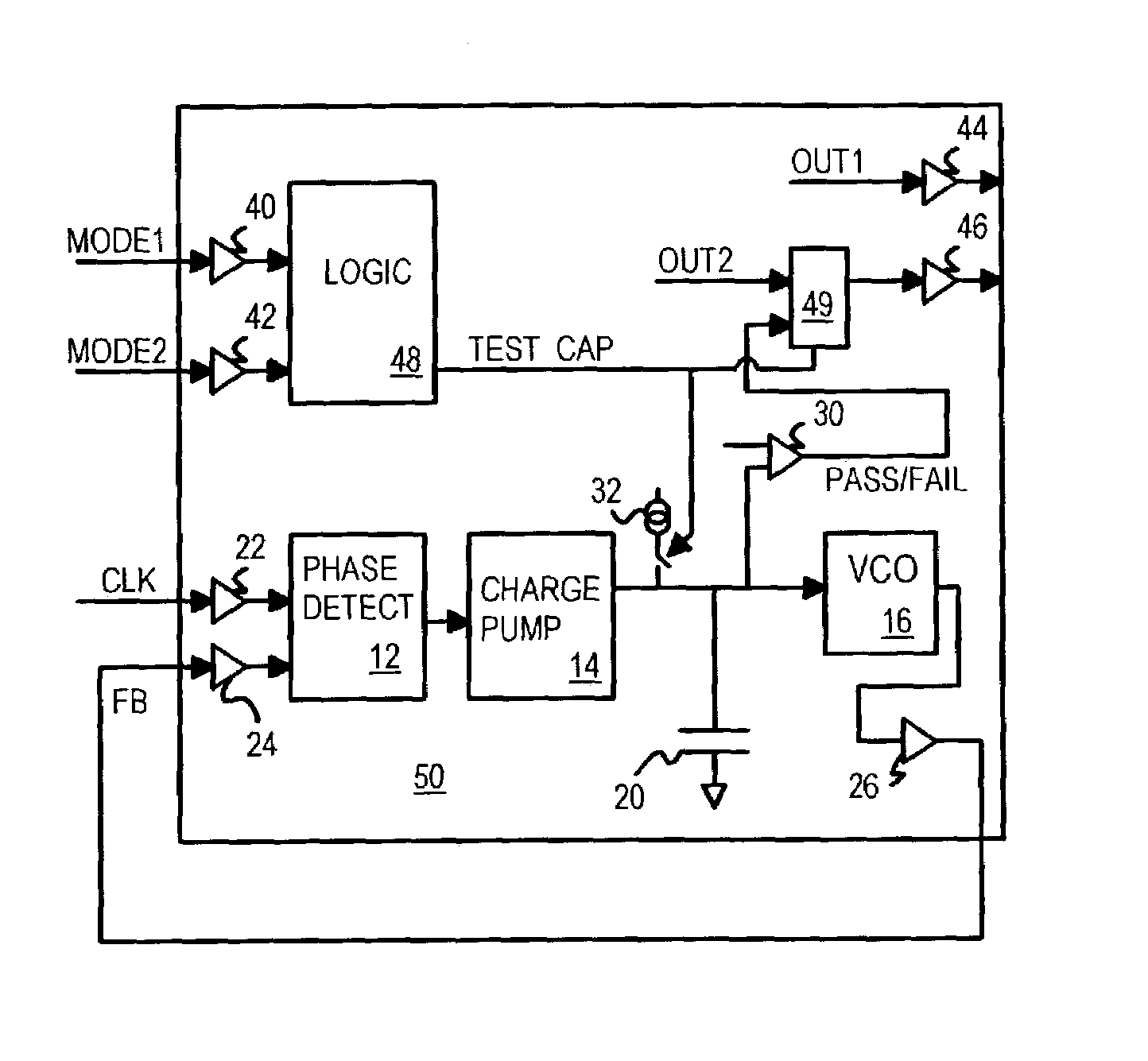
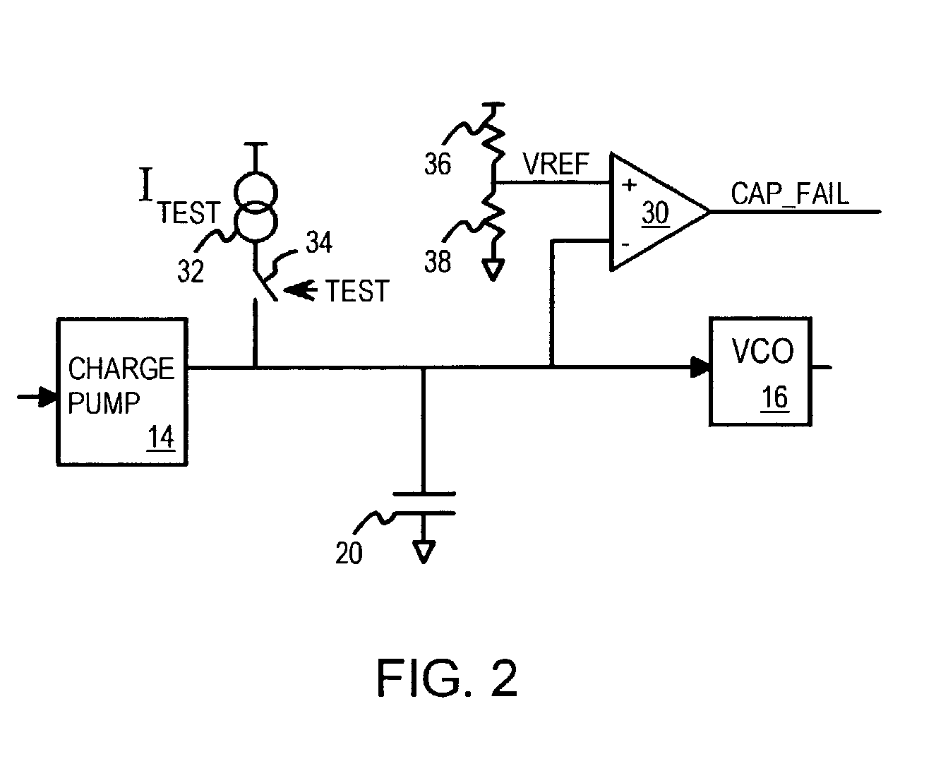
[0017]FIG. 2 is a diagram of a portion of a phase-locked loop (PLL) with a built-in test circuit for testing the filter capacitor. Charge pump 14 sinks and sources current to capacitor 20 during normal operation of the PLL. As capacitor 20 is charged and discharged, the voltage across capacitor 20 changes and voltage-controlled osci...


PUM


Abstract

A filter capacitor within a phase-locked loop (PLL) can be tested using a built-in test circuit. The PLL's charge pump is deactivated while a test-current source is activated to supply a test current to the PLL filter capacitor. When the test current is larger than any leakage currents through the capacitor, the capacitor's voltage rises above a reference voltage. A test comparator compares the capacitor's voltage to the reference voltage and signals a good test result when the capacitor's voltage rises above the reference voltage. When leakage current is larger than the test current, the capacitor's voltage cannot rise above the reference voltage and the test comparator signal a leakage failure. The test current source can share a bias voltage with the charge pump and can drive the capacitor to a voltage higher than the charge pump does to increase leakage and stress during testing.

Description

BACKGROUND OF INVENTION[0001]This invention relates to phase-locked loops (PLL's), and more particularly to built-in test circuits for PLL's.[0002]Many of today's complex electronic systems operate synchronously and require generation of one or more clocks. Phase-locked loops (PLL's) are often employed to generate such clocks from a clock source such as a crystal oscillator. While PLL's can be sold as stand-alone integrated circuit (IC) chips, often PLLs are integrated with many other circuits on a very-large-scale-integration (VLSI) chip.[0003]The cost of manufacturing such IC chips is related to the manufacturing yield. Yield is limited because small particles such as dust can land on the surface of the chip during processing, resulting in a point defect. Other causes of such point defects may include impurities in manufacturing chemicals and materials. The number of defects in a device is often proportional to the area of the device. For example, a large-area capacitor is more li...

Claims


Application Information

Patent Timeline
IPC IPC(8): G01R31/08G01R31/14
CPCG01R31/3004G01R31/31727G11C29/02G11C29/023G11C29/028H03L7/093
Inventor ARCUS, CHRISTOPHER G.
Owner DIODES INC
Why Eureka
Try Eureka