Chopper chopper-stabilized instrumentation and operational amplifiers

a technology of instrumentation amplifiers and stabilizers, applied in the direction of amplifiers with semiconductor devices/discharge tubes, electronic switching, pulse techniques, etc., can solve the problems of limited common-mode rejection ratio (cmrr), inability to include the negative rail in the input voltage common-mode range, and several limitations

Active Publication Date: 2006-11-07
MAXIM INTEGRATED PROD INC
View PDF5 Cites 53 Cited by
  • Summary
  • Abstract
  • Description
  • Claims
  • Application Information

AI Technical Summary

Problems solved by technology

This configuration has two main disadvantages: Firstly, the common-mode rejection ratio (CMRR) is limited by the unbalance of the resistive bridge.
Secondly, the input voltage common-mode (CM) range cannot include the negative rail because of the overall feedback from the output to the input by the OpAmps (“Operational Amplifiers”, Johan Huijsing, Kluwer Academic Publishers).
But there are several limitations.
Secondly, there are several effects that limit the offset reduction.
Another is an unbalance of the charge injection in the choppers by the switching signal.
Further, the initial offset will not fully be averaged out due to parasitic capacitors between the first chopper inputs in combination with attenuation resistors at the inputs.
Trimming is undesirable and not preferred in mass-production due to additional test time, cost and complexity, and lack of stability over temperature and time.

Method used


Image

  • Chopper chopper-stabilized instrumentation and operational amplifiers
  • Chopper chopper-stabilized instrumentation and operational amplifiers
  • Chopper chopper-stabilized instrumentation and operational amplifiers

Examples


Embodiment Construction

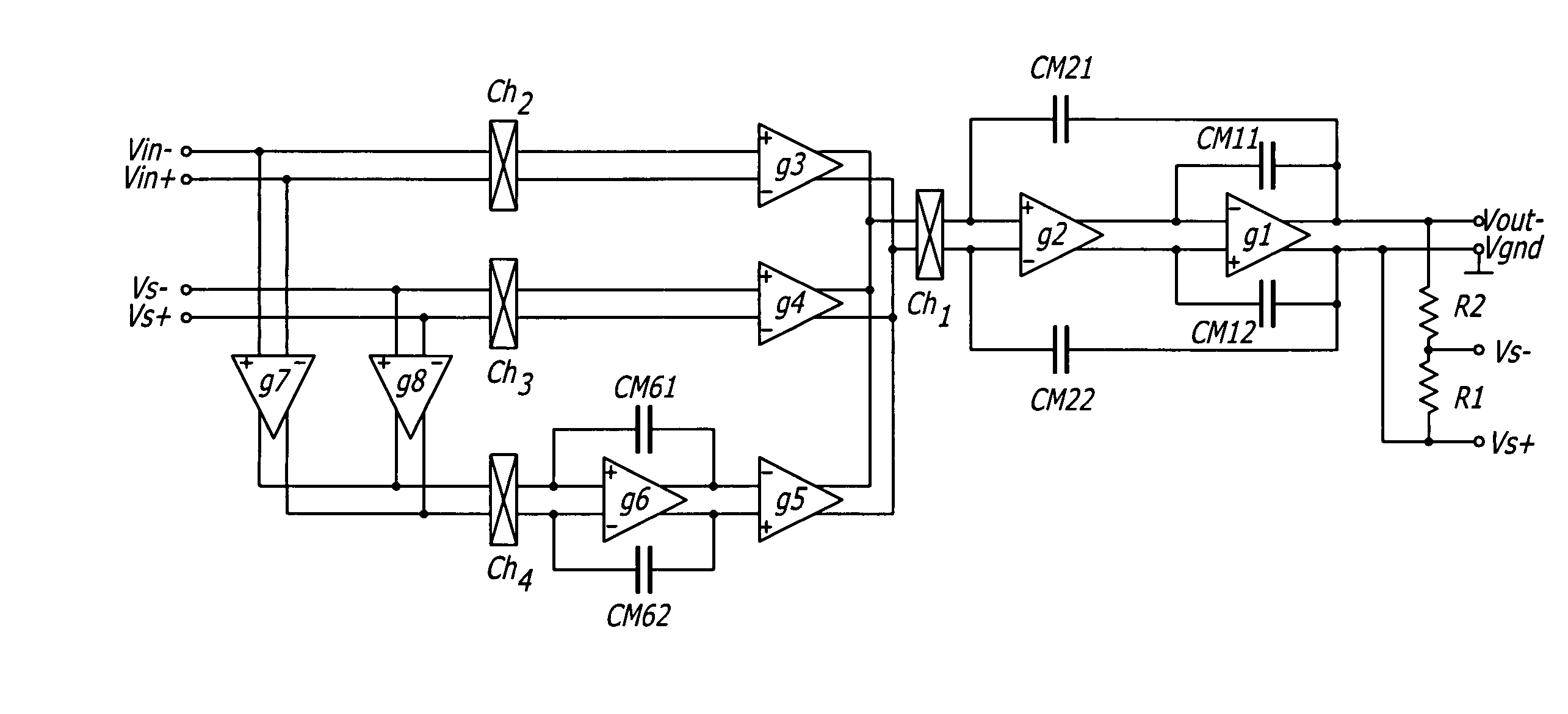
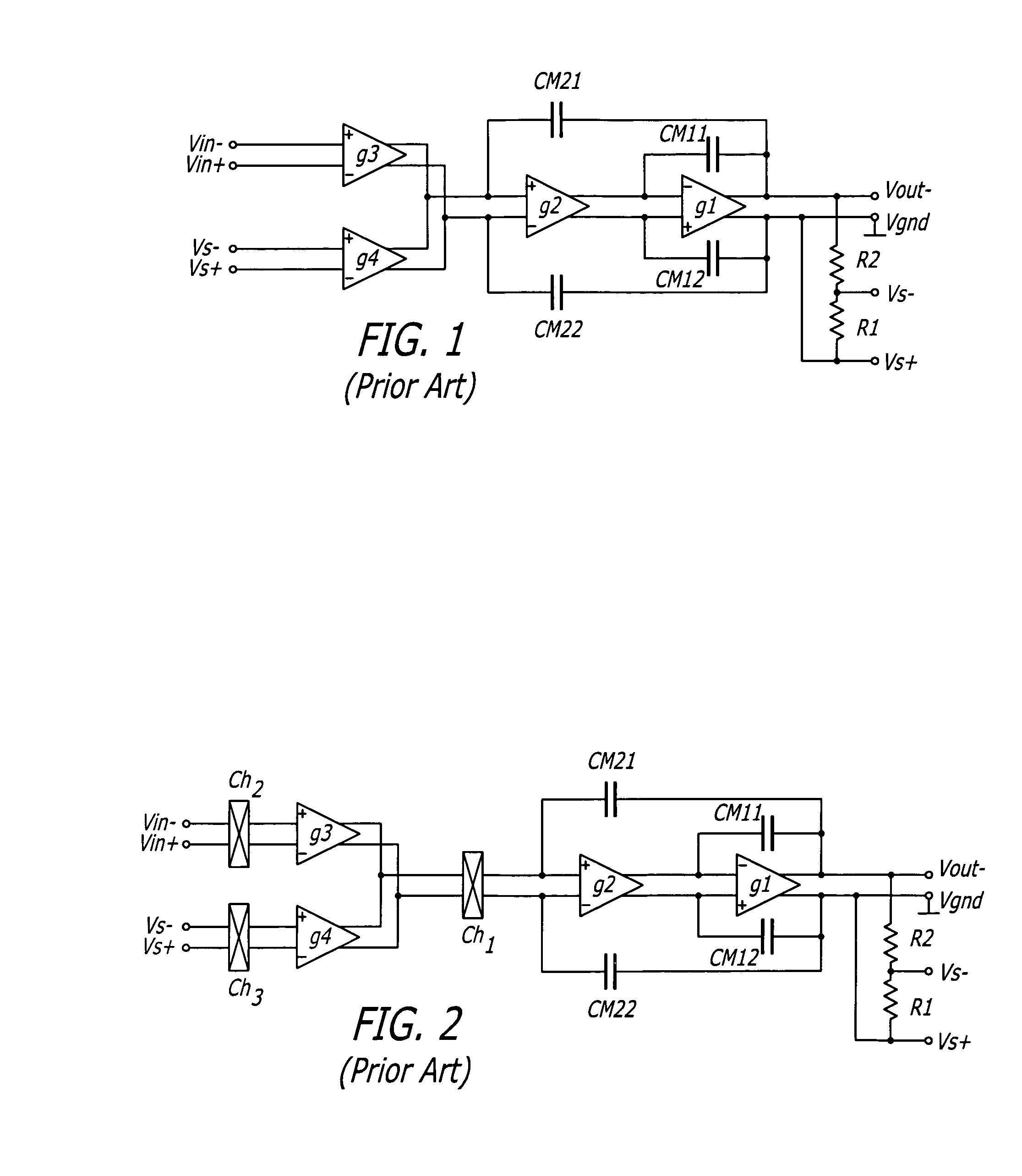
[0018]One embodiment of the present invention is shown in FIG. 4. The basic chopper current-feedback instrumentation amplifier of FIG. 2 is used as the main instrumentation amplifier. The voltage-to-current converter G3 senses the input signal Vin=Vin+−Vin−, while the voltage-to-current converter G4 takes the sense feedback output signal Vs=Vs+−Vs−. If G3=G4, the high loop gain of the whole amplifier forces the feedback sense voltage Vs to be equal and opposite to the input voltage Vin.

[0019]The choppers Ch1, Ch2 and Ch3 chop the offset voltage of the amplifiers G3 and G4. The chopped offset can be regarded as a square-wave interference voltage referred to the input voltage of amplifiers G3 and G4. The input voltage Vin is determined by an external source, and while generally may be a varying signal, it does not contain the square-wave signal. The high loop gain of the whole amplifier forces the feedback-sense voltage Vs to compensate the chopped input offset voltage. Therefore, thi...


PUM


Abstract

Chopper chopper-stabilized instrumentation and operational amplifiers having ultra low offset. The instrumentation amplifiers use current-feedback, and include, in addition to a main chopper amplifier chain, a chopper stabilized loop for correcting for the offset of the input amplifiers for the input signal and for receiving the feedback of the output voltage sense signal. Additional loops, which may include offset compensation and autozeroing loops, may be added to compensate for offsets in the chopper stabilized loop for correcting for the offset of the input amplifiers. Similar compensation is disclosed for decreasing the offset in operational amplifiers.

Description

BACKGROUND OF THE INVENTION[0001]1. Field of the Invention[0002]The present invention relates to the field of instrumentation amplifiers.[0003]2. Prior Art[0004]An Instrumentation Amplifier is often made up of 3 operational amplifiers (OpAmps). The first two amplifiers are buffer amplifiers. The third amplifier is an amplifier with a four-resistor bridge as a feedback network. This configuration has two main disadvantages: Firstly, the common-mode rejection ratio (CMRR) is limited by the unbalance of the resistive bridge. Secondly, the input voltage common-mode (CM) range cannot include the negative rail because of the overall feedback from the output to the input by the OpAmps (“Operational Amplifiers”, Johan Huijsing, Kluwer Academic Publishers).[0005]Therefore, the current-feedback instrumentation amplifier is a better alternative. Its topology is shown in FIG. 1. It is excellently suited to allow the negative or positive supply rail voltage to be included into the input common-m...

Claims


Application Information

Patent Timeline
Patent Type & Authority Patents(United States)
IPC IPC(8): H03F1/02
CPCH03F3/005H03F3/387
Inventor HUIJSING, JOHAN HENDRIKSHAHI, BEHZAD
Owner MAXIM INTEGRATED PROD INC
Why Eureka
Try Eureka