Control circuit for DC/DC converter

a control circuit and converter technology, applied in the direction of dc-dc conversion, climate sustainability, power conversion systems, etc., can solve the problems of reducing the efficiency of dc/dc converters, large electrical power consumption becomes a serious problem, and the recirculation diode consumes a large amount of electrical power, so as to achieve low cost, reduce electrical power consumption, and operate at high efficiency

Inactive Publication Date: 2006-11-14
DEVICE ENG +1
View PDF15 Cites 12 Cited by
  • Summary
  • Abstract
  • Description
  • Claims
  • Application Information

AI Technical Summary

Benefits of technology

[0022]In the present invention, a comparison signal is produced on the basis of the voltage at the connection point between the main switching means and the sub switching means in a blank period which is immediately before the main switching means is turned on and in which both the switching means are off; and the voltage state of the connection point is detected through monitoring of the comparison signal so as to control the sub switching means. Therefore, the sub switching means is not required to be controlled in real time at a timing determined on the basis of the clock signal, and the comparator for outputting the comparison signal is not required to be of a high accuracy type. Accordingly, the comparator can be formed of an element which is inexpensive and consumes a smaller amount of electrical power.
[0023]Accordingly, the control circuit can be provided in...

Problems solved by technology

However, when a recirculation diode is used, because of its relatively large forward voltage drop, the recirculation diode consumes a large amount of electrical power, thereby lowering the efficiency of the DC/DC converter.
Such a large electrical power consumption becomes a serious problem when the DC/DC converter is realized in the form of an IC chip in order to reduce the size of the DC/DC converter.
However, in such a DC/DC converter, when the sub switching element is turned off in a mode in which the main switching element is off and the sub switching element is on, there may occur a harmful reverse flow phenomenon in which current stemming from the electrical energy accumulated in the reactor flows to a DC power source via the parasitic...

Method used


Image

  • Control circuit for DC/DC converter
  • Control circuit for DC/DC converter
  • Control circuit for DC/DC converter

Examples


first embodiment

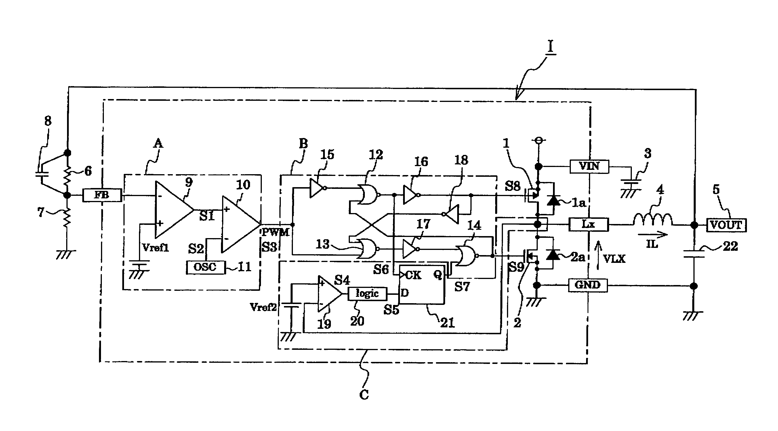
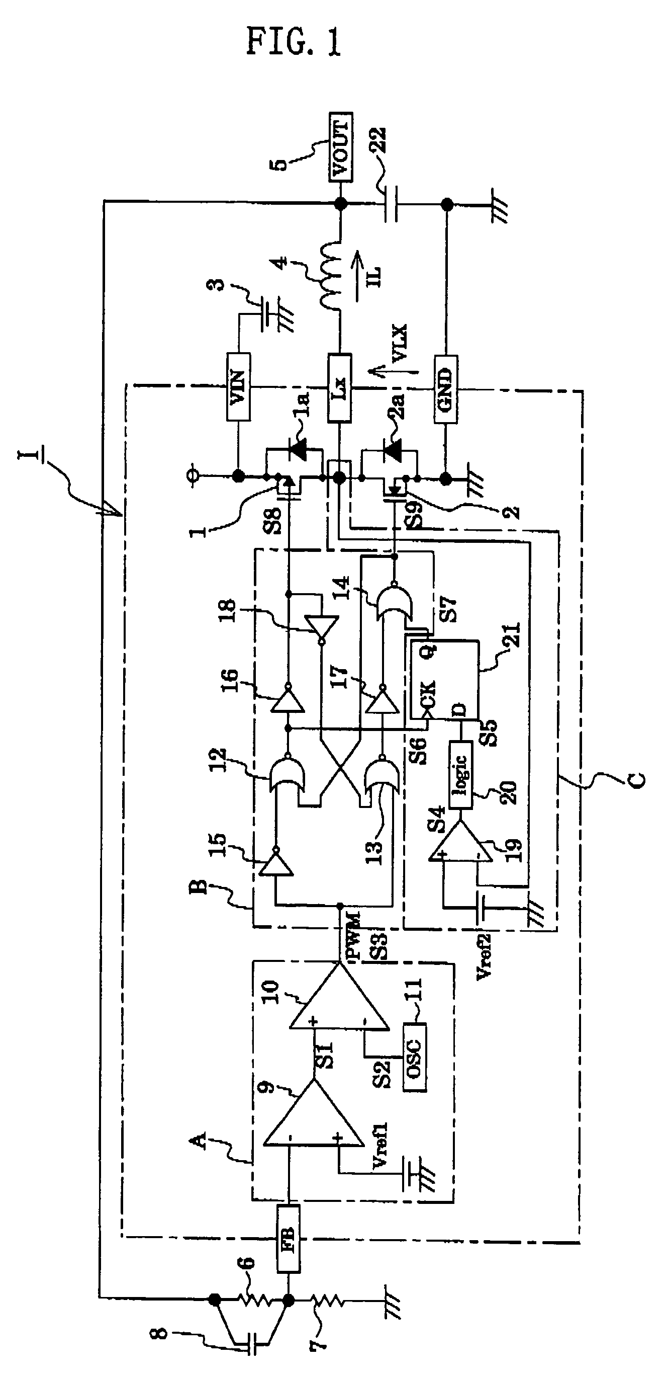
[0037]Before description of a control circuit according to the present embodiment, a main circuit of a DC / DC converter to which the control circuit is applied will be described. FIG. 1 is a circuit diagram showing a control circuit for a DC / DC converter according to a first embodiment of the present invention, along with the main circuit thereof.

[0038]The DC / DC converter according to the present embodiment is a step-down converter. In the DC / DC converter, a MOSFET 1, which serves as main switching means and to which a parasitic diode 1a is connected in parallel and in the reverse direction, and a reactor 4 are connected in series. Meanwhile, a MOSFET 2, which serves as sub switching means and to which a parasitic diode 2a functioning as a recirculation diode is connected in parallel, is connected to the point of connection between the MOSFET 1 and the reactor 4. A DC output voltage VOUT is extracted via the reactor 4 and an output terminal 5. A DC power source 3 is formed of a prima...

second embodiment

[0080]Before description of a control circuit according to the present embodiment, a main circuit of a DC / DC converter to which the control circuit is applied will be described. FIG. 6 is a circuit diagram showing a control circuit for a DC / DC converter according to a second embodiment of the present invention, along with the main circuit thereof.

[0081]The DC / DC converter according to the present embodiment is a step-up converter. In the DC / DC converter, a reactor 34 is connected in series to a MOSFET 32, which serves as sub switching means and to which a diode 32a is connected in parallel. A DC power source 33 is connected is series to the reactor 34 and the MOSFET 32. Meanwhile, a MOSFET 31, which serves as main switching means and to which a diode 31a is connected in parallel and in the reverse direction, is connected to the point of connection between the reactor 34 and the MOSFET 32.

[0082]In such a DC / DC converter, the MOSFETs 31 and 32 are controlled such that they are alterna...


PUM


Abstract

A control circuit for a DC/DC converter which includes a main switching element, a sub switching element, and a reactor in order to convert a DC input voltage to a DC output voltage. The control circuit comprises a clock signal generator for generating a clock signal during a blank period in which both the main and sub switching elements are off; a comparator for comparing a reference voltage and a voltage at a connection point between the main and sub switching elements and for outputting a comparison signal indicating a relation of magnitude between the reference voltage and the voltage at the connection point; and an operation mode switching section for monitoring the comparison signal at a timing corresponding to the clock signal in order to detect a voltage state at the connection point, and controlling the sub switching element in accordance with the voltage state.

Description

BACKGROUND OF THE INVENTION[0001]1. Field of the Invention[0002]The present invention relates to a control circuit for a DC / DC converter, and more particularly to a control circuit for a DC / DC converter in which main switching means and sub switching means are alternately turned on and off so as to obtain a predetermined DC output voltage.[0003]2. Description of the Related Art[0004]DC / DC converters are widely used in applications in which output voltage of a DC power source is stepped down or up so as to obtain a predetermined DC output voltage; e.g., a power supply circuit for a cellular phone. In such a DC / DC converter, a switching element is turned on and off, and the on / off operation of the switching element is controlled in order to convert a DC input voltage to a predetermined DC output voltage. In general, a MOSFET is used as a switching element.[0005]Among DC / DC converters of such a type, a step-down DC / DC converter has a reactor on the output side. Therefore, in periods du...

Claims


Application Information

Patent Timeline
IPC IPC(8): G05F1/56H02M3/155H02M3/158
CPCH02M3/1588Y02B70/1466Y02B70/10
Inventor HANE, NORIMASAOHKAWA, SATORUNAKA, TAKESHI
Owner DEVICE ENG
Why Eureka
Try Eureka