Occupant presence detection device

a detection device and occupant technology, applied in the field of safety systems, can solve the problems of complex circuitry, high cost and complexity of these devices, and require precision components, and achieve the effect of high precision components

Inactive Publication Date: 2006-11-14
INTELLIGENT MECHANTRONIC SYST INC
View PDF65 Cites 73 Cited by
  • Summary
  • Abstract
  • Description
  • Claims
  • Application Information

AI Technical Summary

Benefits of technology

[0006]The purpose of the present invention is to provide an occupant detection device, which avoids the use of mechanical sensing apparatuses, and is less expensive and more reliable than existing capacitive based occupant sensing systems. The present invention includes a single conductive electrode which, in conjunction with its surroundings, forms a capacitor which is a part of a bridge circuit. The device includes an oscillator for continuous excitation of the bridge, a differential amplifier to determine if the bridge is unbalanced, an AC-DC converter circuit to convert the output of the amplifier to a DC signal, and a threshold circuit for triggering the output signal once the output of the AC-DC converter exceeds a predetermined threshold.
[0008]If an occupant is present on the seat, additional capacitance from the human body is introduced into the bridge via the electrode. This creates differences in the voltage and phase of the waveform in each arm of the bridge circuit. These changes are then amplified by a differential amplifier. The signal is then converted to a DC voltage that, when above a predetermined threshold, causes the device to output a signal that indicates the presence of an occupant. Using a bridge configuration and a differential amplifier allows the circuit to be operated over a wide range of supply voltages. It also reduces the need for high precision components and the need to regulate the amplitude of the waveform produced by the oscillator.

Problems solved by technology

However, many of these devices, which claim to be inexpensive, use circuitry that is far more complex than the circuitry of the device described herein.
They may require precision components and may only function over a small range of supply voltages.
This adds a great deal of cost and complexity to these devices in comparison with this invention.
Furthermore, some devices, such as the device described in U.S. Pat. No. 4,796,013, cannot accurately detect whether the electrode is disconnected or damaged and will determine this situation to be an empty seat regardless of whether an occupant is present or not.
This could prove to be fatal when the device is being used to provide logic that enables or disable a safety restraint device, such as an airbag.

Method used


Image

  • Occupant presence detection device
  • Occupant presence detection device
  • Occupant presence detection device

Examples


second embodiment

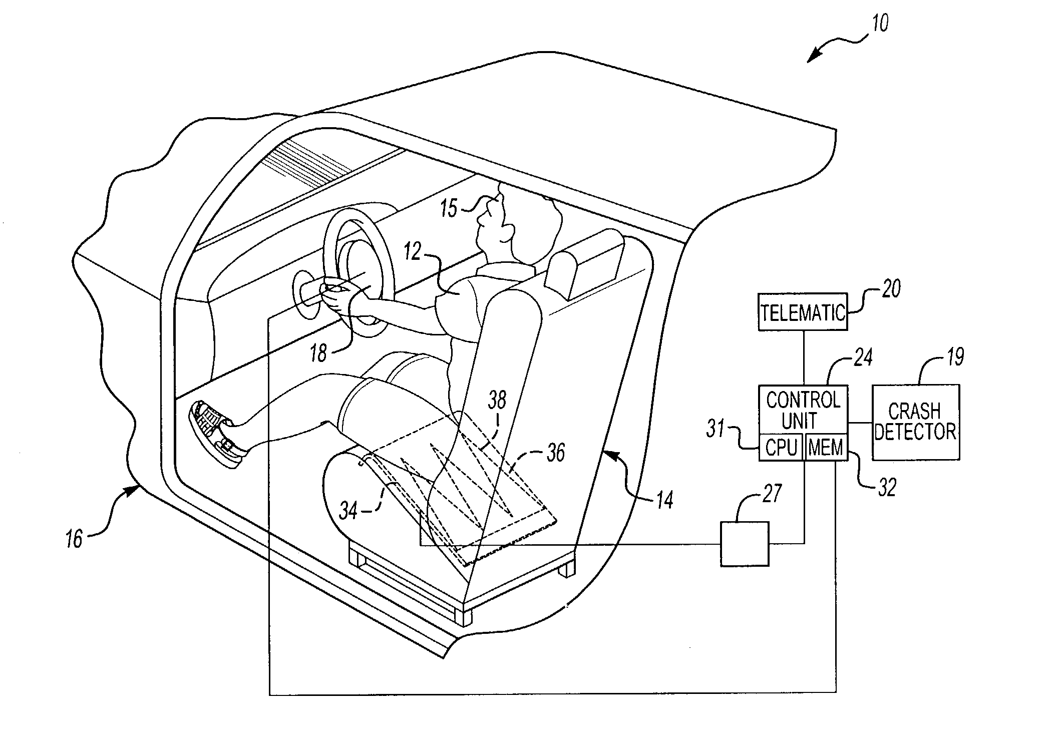
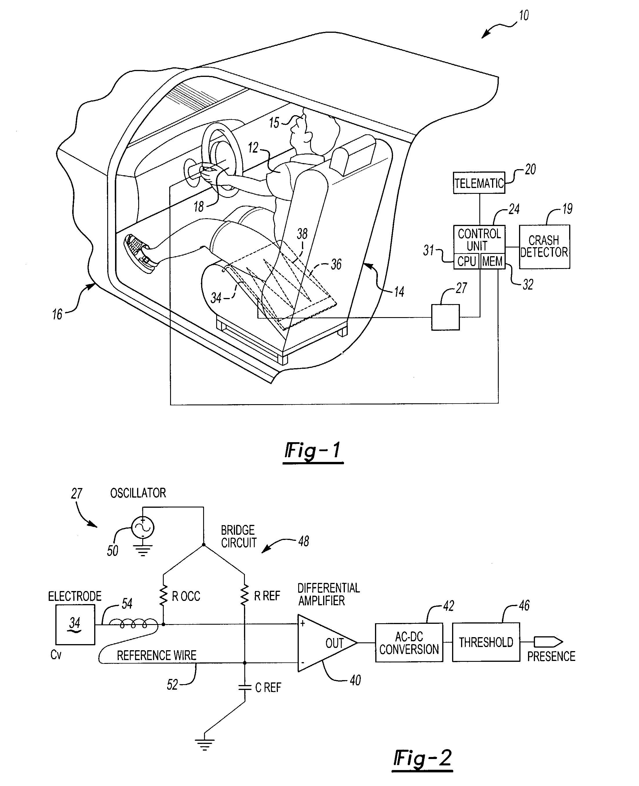
[0036]In the invention, shown in FIG. 5, a fault detection circuit 60 is incorporated to detect the most common failure modes of a capacitance based system. These include; failure of the oscillator 50 disconnected or damaged electrode 34, and the electrode 34 being shorted to the grounded vehicle chassis. This allows for the device reading the occupant presence detection device to take alternative actions in the event of a failure. This device utilizes the electrode 34 shown in FIG. 1.

[0037]The fault detection circuit 60 is divided into two independent modules; an oscillator failure detection module 62 and a damaged / grounded electrode detection module 64. The output of the oscillator 50 is coupled to an AC-DC converter 66 via the capacitor C which only allows an alternating signal to pass. Regardless of the voltage at which the oscillator 50 fails, the signal will not be passed to the AC-DC converter 66 once there is no oscillation. This will cause the DC signal to fall below a pred...

third embodiment

[0040]In the invention, shown in FIGS. 6a and 6b, a second capacitive sensor 80, configured to detect pressure, is used in conjunction with the original electrode in order to detect the presence of a child-seat. FIG. 6a shows the TOP and SIDE view of the sensor. It consists of a basic occupant sensing electrode 34 (as described above) working in conjunction with the pressure-sensing capacitive sensor 80. The capacitive sensor 80 comprises a sensing electrode 82, a grounded plate 84 and a compressible material 86.

[0041]As mentioned previously, a decrease in the distance between the electrodes 82, 84 causes an increase in capacitance. Therefore, the weight of a body, or of a child seat will cause the distance between the sensing electrode 82 and grounded electrode 84 to decrease, causing an increase in capacitance. This will be detected by the second detection circuit 90 as shown in FIG. 6b.

[0042]The second detection circuit 90 is identical to the first, only it is configured to dete...


PUM


Abstract

The purpose of this invention is to sense the presence of a seated occupant in a vehicle such as an automobile, plane, train or bus, or in a room or location where it is desirable to detect if seats are occupied. The occupant presence detection device consists of a single seat-mounted electrode, an oscillator circuit, a bridge circuit, a detection circuit and a circuit for processing the detected signals. The oscillator circuit excites the electrode. If an occupant is present on the seat, additional capacitance from the human body is introduced into the bridge via the electrode. This created differences in the voltage and phase of the waveform in each arm of the bridge circuit which are amplified by a differential amplifier. The signal is then converted to a DC voltage that, when above a predetermined threshold, causes the device to outputs a signal that indicates the presence of an occupant. Using a bridge configuration and a differential amplifier allows the circuit to be operated over a wide range of supply voltages. It also reduces the need for high precision components and the need to regulate the amplitude of the waveform produced by the oscillator. The net result is a capacitive occupant sensing device that is less complex and less expensive that previous capacitive occupant sensing devices, yet is tolerant of power supply fluctuations, is able to function over a wide range of operating voltage and still provides failsafe functionality.

Description

[0001]This application claims priority to U.S. Provisional Patent Application Ser. No. 60 / 341,123, filed Dec. 13, 2001.BACKGROUND OF THE INVENTION[0002]The present invention relates to safety systems and more particularly to capacitive occupancy detection devices. Occupant detection devices can be used to enable or disable a safety restraint device, such as an airbag, or to determine how many occupants are present in a vehicle or a room. These devices can be used to detect the absence of an occupant in the passenger seat of a vehicle, and thereby disable the deployment of the passenger's airbag. The number of occupants in a vehicle may also be monitored prior to an accident in order to provide a telematic unit, such as Onstar®, with an occupant count in order to dispatch an adequate amount of emergency response. Having an accurate occupant count prior to an accident can also help emergency response personnel to determine if one or several of the occupants may have been ejected from ...

Claims


Application Information

Patent Timeline
Patent Type & Authority Patents(United States)
IPC IPC(8): G08B21/00B60N2/90B60N2/00B60R21/01B60R21/015B60R21/16B60R22/46G01G19/414
CPCB60N2/002B60R21/01516G01G19/4142B60R21/01532B60R2021/01156B60R2021/01163H03K2217/96075B60R2021/0117
Inventor FILIPPOV, VLADIMIRDESROCHERS, KRISTOPHERSTEPANOV, VALERIBASIR, OTMAN ADAMKARRAY, FAKHREDDINE
Owner INTELLIGENT MECHANTRONIC SYST INC
Why Eureka
Try Eureka