
Programmer and surface ECG system with wireless communication

a programmable and wireless communication technology, applied in the field of cardiac monitoring devices, can solve the problems of increasing the cost and complexity of programmers, emi and common-mode signals degrade the accuracy of ecg signals, and subject to electromagnetic interference (emi)

Inactive Publication Date: 2006-11-14
PACESETTER INC
View PDF18 Cites 57 Cited by
  • Summary
  • Abstract
  • Description
  • Claims
  • Application Information

AI Technical Summary

Benefits of technology

[0022]In addition, the implantable device and the programmer can communicate via first wireless communication means and the programmer and the monitoring means can communicate via second wireless communication means. This can occur such that at least one of the first and second wireless communications means operate in the 900 MHz band. These and other objects and advantages will be more apparent from the following description taken in conjunction with the accompanying drawings.

Problems solved by technology

As the programmer is thus electrically coupled to the patient, it is subject to exposure to electromagnetic interference (EMI) that may surround the interconnection.
Both EMI and common-mode signals degrade the accuracy of the ECG signal.
The inclusion of such protection circuitry increases the cost and complexity of programmers.
The interconnection cable employed in prior art programmers with surface ECG systems presents some further difficulties in use for the clinician and for the patient.
The cable is physically attached to the patient and impairs their movement in bed and can become entangled with bedding, I.V. tubes, etc.
The cables present a tripping hazard as well as a potential cause of upset and damage to the programmer or other devices that may be placed on tables or carts.
Another disadvantage of present programmer / ECG systems is that the clinician must physically connect the programmer to surface electrodes with the interconnection cable each time he visits a new patient.
Often an individual programmer is not available for each patient due to cost considerations and the clinician must move a single programmer with him as he visits patients.
It can be appreciated that disconnecting and reconnecting the cables each time a clinician visits a patient consumes the doctor's valuable time as well as presents a cause of wear and tear on the cables and connectors.

Method used


Image

  • Programmer and surface ECG system with wireless communication
  • Programmer and surface ECG system with wireless communication
  • Programmer and surface ECG system with wireless communication

Examples


Embodiment Construction

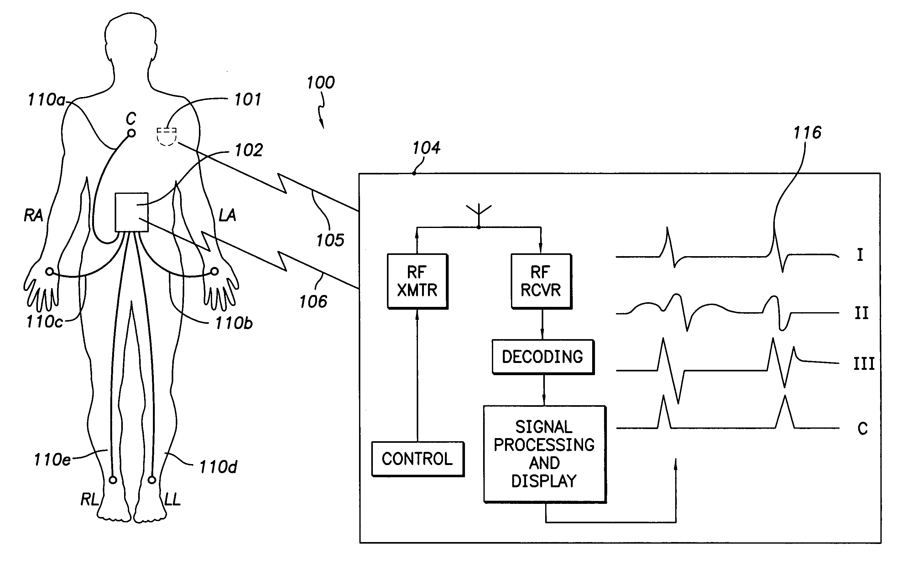
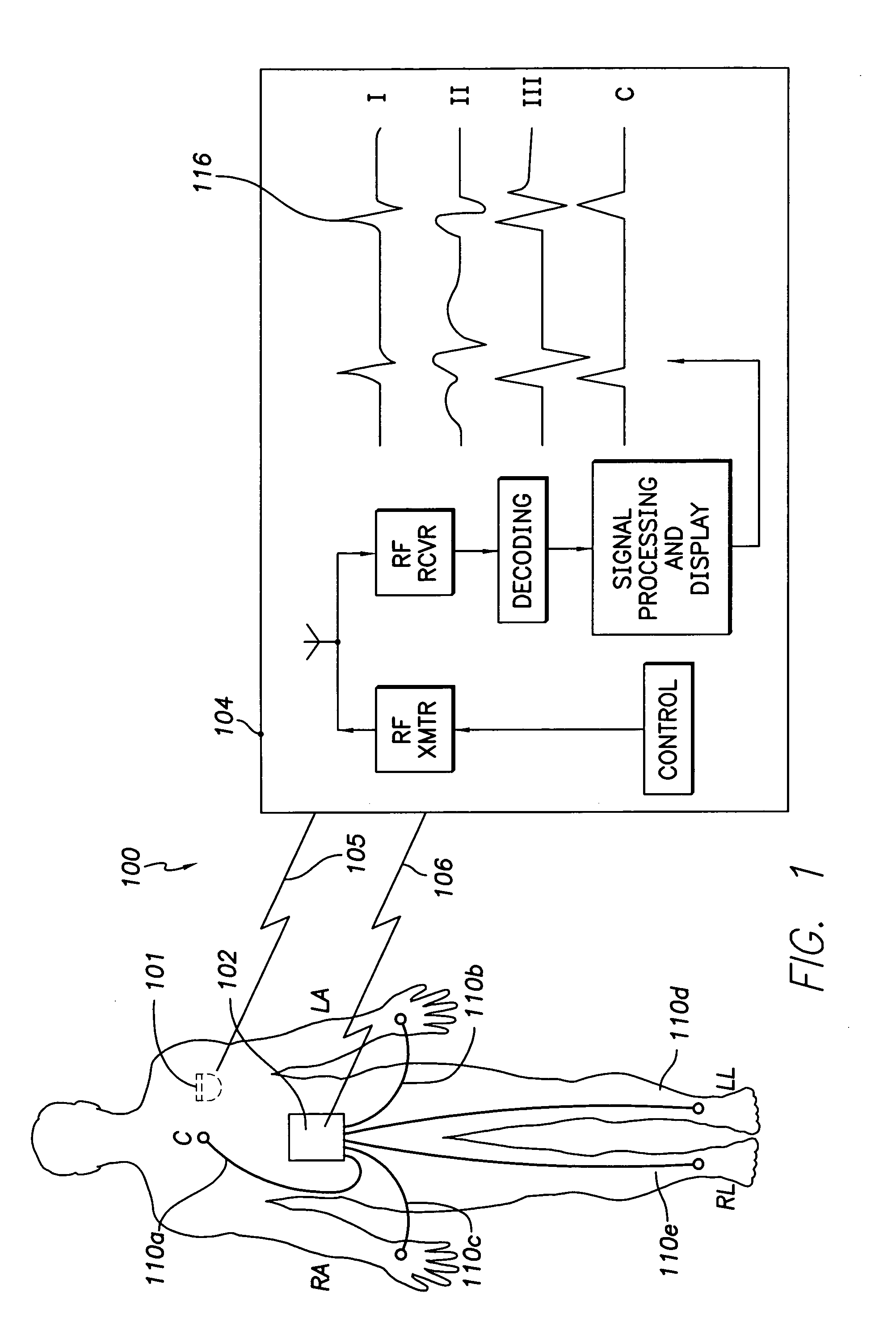
[0030]Reference will now be made to the drawings wherein like numerals refer to like parts throughout. FIG. 1 illustrates a programmer for implantable cardiac devices and surface electrocardiogram (ECG) monitor with wireless communication system 100 referred to hereafter as “system 100” for brevity. The system 100 enables a clinician to program and retrieve information from an implantable stimulation device (not shown) via a first telemetric link 105 and to receive and control surface ECG signals in a wireless fashion from the patient via a second telemetric link 106 in a manner that will be described in greater detail below.

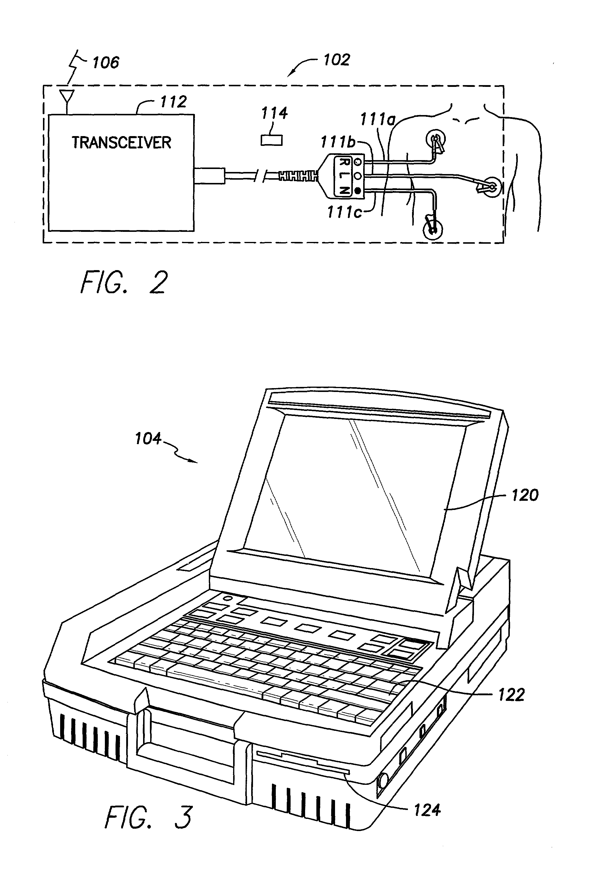
[0031]The system 100 comprises an ECG monitor 102 that monitors surface ECG signals of a patient's body and selectively transmits those signals to a remote programmer 104 via the second telemetric link 106. The second telemetric link 106 reduces the need for the hardwiring of the prior art between an ECG monitor and a programmer while enabling the surface ECG mo...


PUM


Abstract

A programmer for implantable stimulation devices and surface ECG system in wireless communication with each other. A self-powered ECG monitor with conventional surface electrodes transceives signals from and to a programmer provided with a radio frequency transceiver to eliminate hardwiring between the surface electrodes and the programmer. The system reduces the need for supply line frequency filtering and isolation circuitry to protect against high voltage defibrillation shocks.

Description

FIELD OF THE INVENTION[0001]The present invention relates to the field of cardiac monitoring devices and, in particular, to a combined programmer for implantable cardiac devices and a surface ECG system with a wireless communication capability with the programmer.BACKGROUND OF THE INVENTION[0002]The ongoing clinical care provided to patients with implantable cardiac device systems often includes the use of surface electrocardiograms (ECG). An ECG is a highly useful diagnostic aid for clinicians for the study of heart rate and rhythm. The ECG indicates the propagation of low amplitude electrical signals, commonly referred to as the cardiac impulse, across the myocardium giving information about depolarization and repolarization characteristics of the heart.[0003]An ECG typically receives signals from a plurality of electrodes (3, 5, and 12 are common numbers) that are placed on the patient's skin surface. The ECG monitors voltage signals appearing between various pairs of the electro...

Claims


Application Information

Patent Timeline
Patent Type & Authority Patents(United States)
IPC IPC(8): A61N1/362
CPCA61N1/37211A61N1/37247A61N1/37252
Inventor CAPPA, ARMANDO M.SILVIAN, SERGIULEVINE, PAUL A.
Owner PACESETTER INC
Learn More