Tube assembly for a boiler

a technology of boilers and tubes, applied in the direction of steam boiler components, fire-box steam boilers, energy industry, etc., can solve the problems of increased costs and increased costs, and achieve the effects of improving system efficiency, increasing boiler efficiency, and increasing heat transfer coefficients

Inactive Publication Date: 2006-11-21
PRIME BOILERS
View PDF5 Cites 22 Cited by
  • Summary
  • Abstract
  • Description
  • Claims
  • Application Information

AI Technical Summary

Benefits of technology

[0006]The inventors have realized that it is possible to increase the efficiency of a boiler by using a unique, parallel flow design in which the flow of the flue gas (i.e. hot gases) is parallel to the direction of at least a portion of the tube runs of the water tubes. This orientation allows for more direct radiant heat towards the water tubes resulting in greater heat transfer coefficients and improved system efficiency. In addition, the orientation allows for a smaller flow path, and thus a smaller size boiler, for producing the same amount of heat as compared to a larger, conventional boiler. The inventors have also found that it is advantageous to fire a flue gas flame directly towards an end wall composed of tubes of a portion of the tube assembly for more direct heat transfer as well as removing the need for refractory material in this portion of a boiler.

Problems solved by technology

However, to obtain a higher throughput of heated water or generated steam, either a higher efficiency boiler is needed, which, if conventionally designed, results in increased costs due to the need for additional more expensive equipment, or a larger boiler is needed which also results in increased costs due to the need for more material.

Method used


Image

  • Tube assembly for a boiler
  • Tube assembly for a boiler
  • Tube assembly for a boiler

Examples


Embodiment Construction

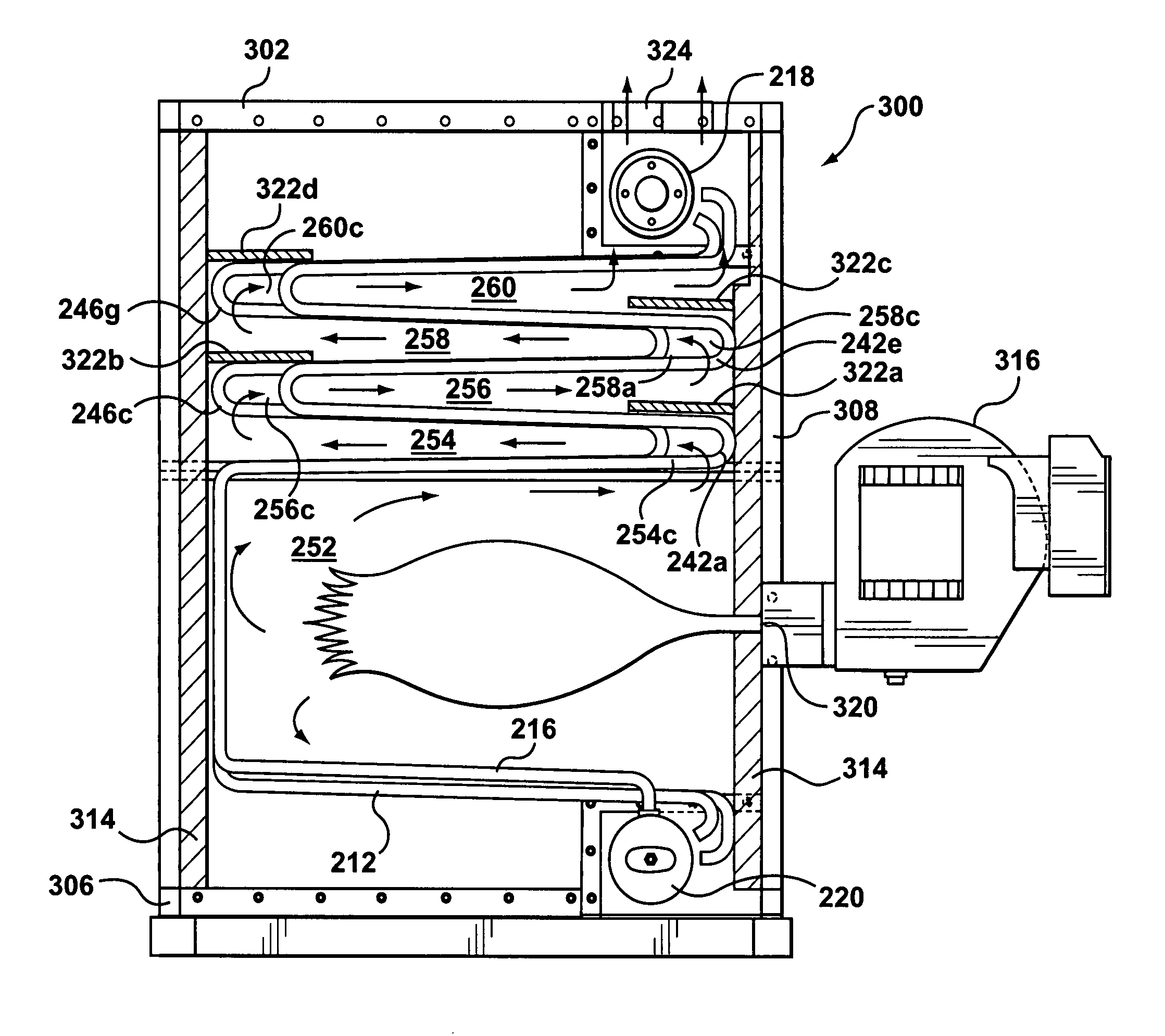
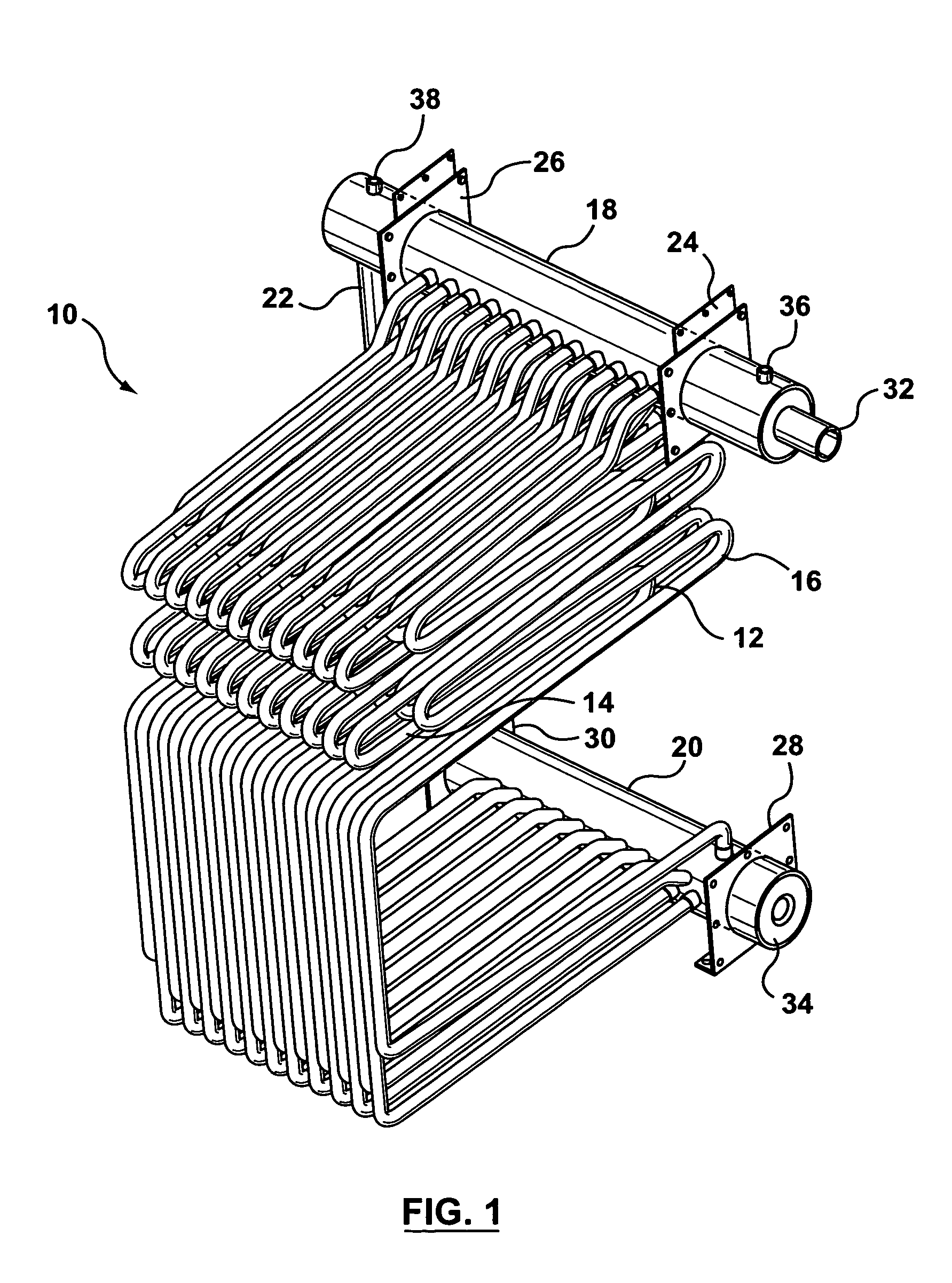
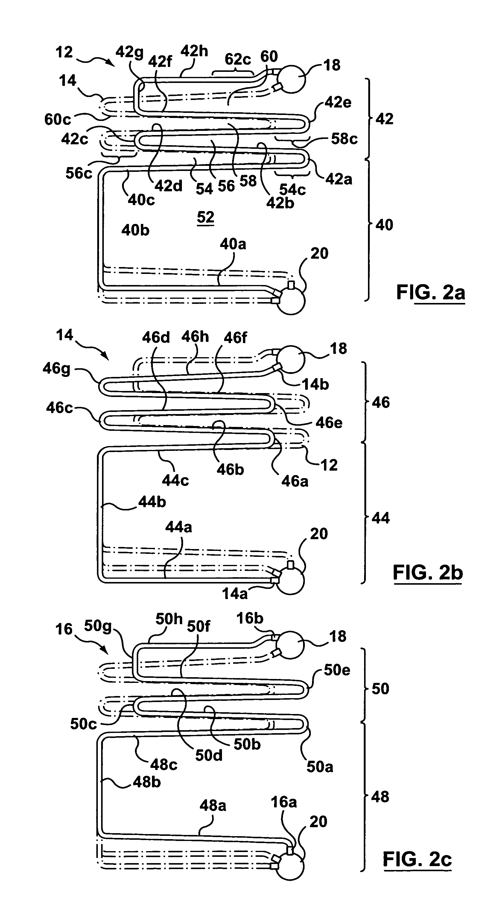
[0026]Referring now to FIG. 1, shown therein is a tube assembly 10, in accordance with the invention, for use in a boiler. The tube assembly 10 comprises a plurality of tubes of which there are generally three types, i.e. tube types 12, 14 and 16, which each have a unique shape. The shape and fashion in which the three different types of tubes 12, 14 and 16 are horizontally stacked to construct the tube assembly 10 results in improved heat transfer for flue gas pathways in a boiler which employs the tube assembly 10. This is discussed in further detail below and shown in FIG. 3.

[0027]The tube assembly 10 is connected to an upper drum (i.e. manifold) 18 and a lower drum (i.e. manifold) 20. The upper and lower drums 18 and 20 are also connected to each other by a downcomer pipe 22. The upper drum 18 and the lower drum 20 are generally in a horizontal configuration. The upper drum 18 also has support members 24 and 26 and the lower drum 20 has support members 28 and 30 for mounting the...


PUM


Abstract

A boiler is described comprising a housing with a flue gas inlet for receiving a hot gas flame and an outlet for venting a hot gas produced by the hot gas flame, and a tube assembly mounted within the housing. The tube assembly comprises a lower manifold for receiving a liquid, an upper manifold for receiving a heated version of the liquid; and, a plurality of tubes disposed between the lower and upper manifolds. Each tube is shaped to provide a hot gas pathway that travels in a parallel fashion along at least a lower portion of the longitudinal extent of each tube in the tube assembly to the outlet, whereby the liquid introduced into the lower manifold travels in the plurality of tubes and receives heat from the hot gas along the extent of the hot gas pathway.

Description

FIELD OF THE INVENTION[0001]The invention relates to a design for improving heat transfer and system efficiency for a boiler.BACKGROUND OF THE INVENTION[0002]A boiler is a pressurized system in which heat is transferred to a fluid. Water is typically used as the fluid for economical reasons and its suitable thermodynamic characteristics. The water is heated by heat transferred to the water from a source of higher temperature (i.e. a flue gas), which is usually produced by the combustion of fuels. The water may be heated to a suitable temperature or heated such that it is vaporized to a steam. Accordingly, connections are made for the off-take of the heated water or the generated steam and for the replenishment of water. The heated water or generated steam can be used as a heating medium or as a working fluid in another device that converts thermal energy to mechanical work. The water also acts to cool the heat-absorbing surfaces of the boiler while the water circulates through the b...

Claims


Application Information

Patent Timeline
Patent Type & Authority Patents(United States)
IPC IPC(8): F22B15/00
CPCF22B13/04F22B15/00Y02P80/15
Inventor ZORZIT, VITTORIO
Owner PRIME BOILERS
Why Eureka
Try Eureka