
System and method for handling bulk materials

a technology of bulk materials and systems, applied in bulk conveyors, mechanical conveyors, transportation and packaging, etc., can solve the problems of difficult control of flow rates difficult to accurately meter such materials as often required in various processes, and poor flow rate of sluggish and cohesive bulk materials. , to achieve the effect of enhancing material flow, reducing surface friction, and easy control of flow ra

Active Publication Date: 2006-11-21
YOUNG INDS
View PDF19 Cites 29 Cited by
  • Summary
  • Abstract
  • Description
  • Claims
  • Application Information

AI Technical Summary

Benefits of technology

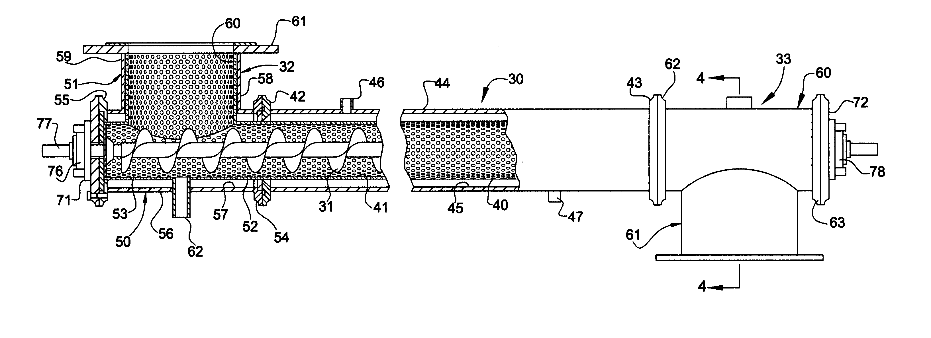
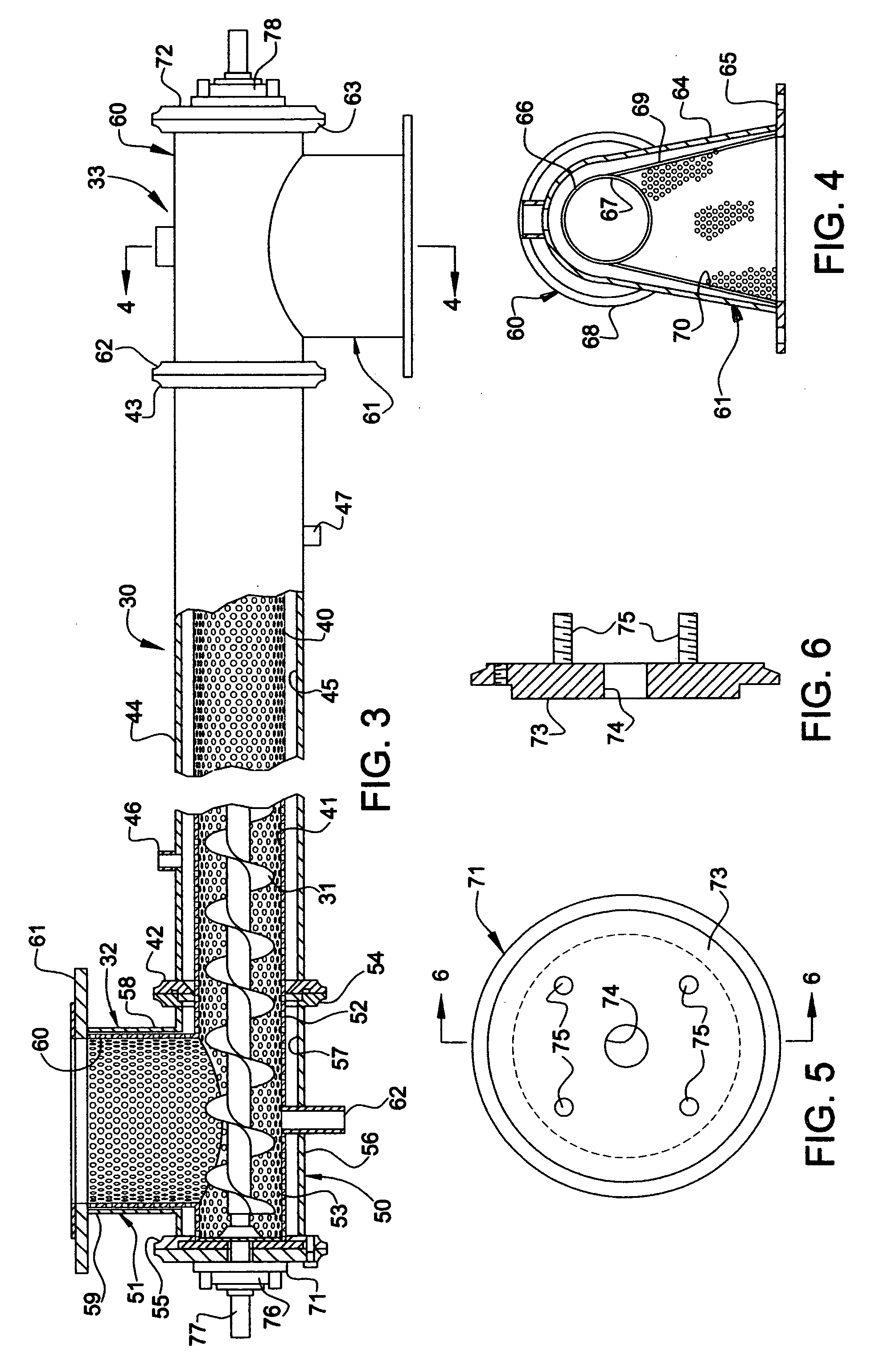
[0003]The principal object of the present invention is achieved by providing a bulk material handling system generally consisting of means for holding a supply of such material; means for conveying the material including a first conduit formed of a permeable material having an inlet communicating with an outlet of a material holding means and an outlet, a second conduit formed of a impermeable material encompassing and spaced from the permeable conduit, providing a chamber therebetween, and an auger disposed in the permeable conduit for transporting material received through the inlet to the outlet thereof; means for rotatably driving the auger; and means for supplying a fluidizing gas under pressure to the chamber whereby such fluidizing gas penetrates the inner permeable conduit encasing the auger, which forms a boundary layer consisting of a mixture of fluidizing gas and particles of the bulk material being conveyed, thus reducing surface friction and correspondingly enhancing the flow of material propelled by the auger. In such an arrangement, the flow rate may be more readily controlled by simply controlling the speed of the drive motor for the auger. More accurate amounts of material may be metered simply by monitoring the feed rate of material being discharged from the screw conveyor, comparing such feed rate with a selected feed rate and correspondingly adjusting such feed rate by controlling the speed of the drive motor for the screw conveyor; monitoring the loss of weight of material fed into the screw conveyor; comparing such loss of weight with a selected weight and adjusting the speed and / or discontinuing the operation of the drive motor; and monitoring a gain of weight of material discharged from such screw conveyor, comparing such weight to a predetermined weight and correspondingly adjusting the speed and / or discontinuing the operation of the drive motor. The supply of fluidizing air to the inner conduit of the screw conveyor surrounding the auger functions not only to improve the flow rate of sluggish and cohesive materials through the screw conveyor but reduces the amount of torque required to drive the auger of the conveyor, permits more precise control of the flow rate and prevents the buildup of material in the conveyor requiring periodic cleaning.

Problems solved by technology

In the use of such conveyors, however, it has been found that the flow rates of sluggish and cohesive bulk materials is poor, the flow rates of such materials are difficult to control, a substantial amount of torque is required to operate such conveyors and such materials tend to build up in the tube around the auger which often is difficult, time consuming and cumbersome to clean.
In addition, because of a lack of control of the flow rates in such conveyors, it is difficult to accurately meter such materials as often is required in various processes.

Method used


Image

  • System and method for handling bulk materials
  • System and method for handling bulk materials
  • System and method for handling bulk materials

Examples


Embodiment Construction

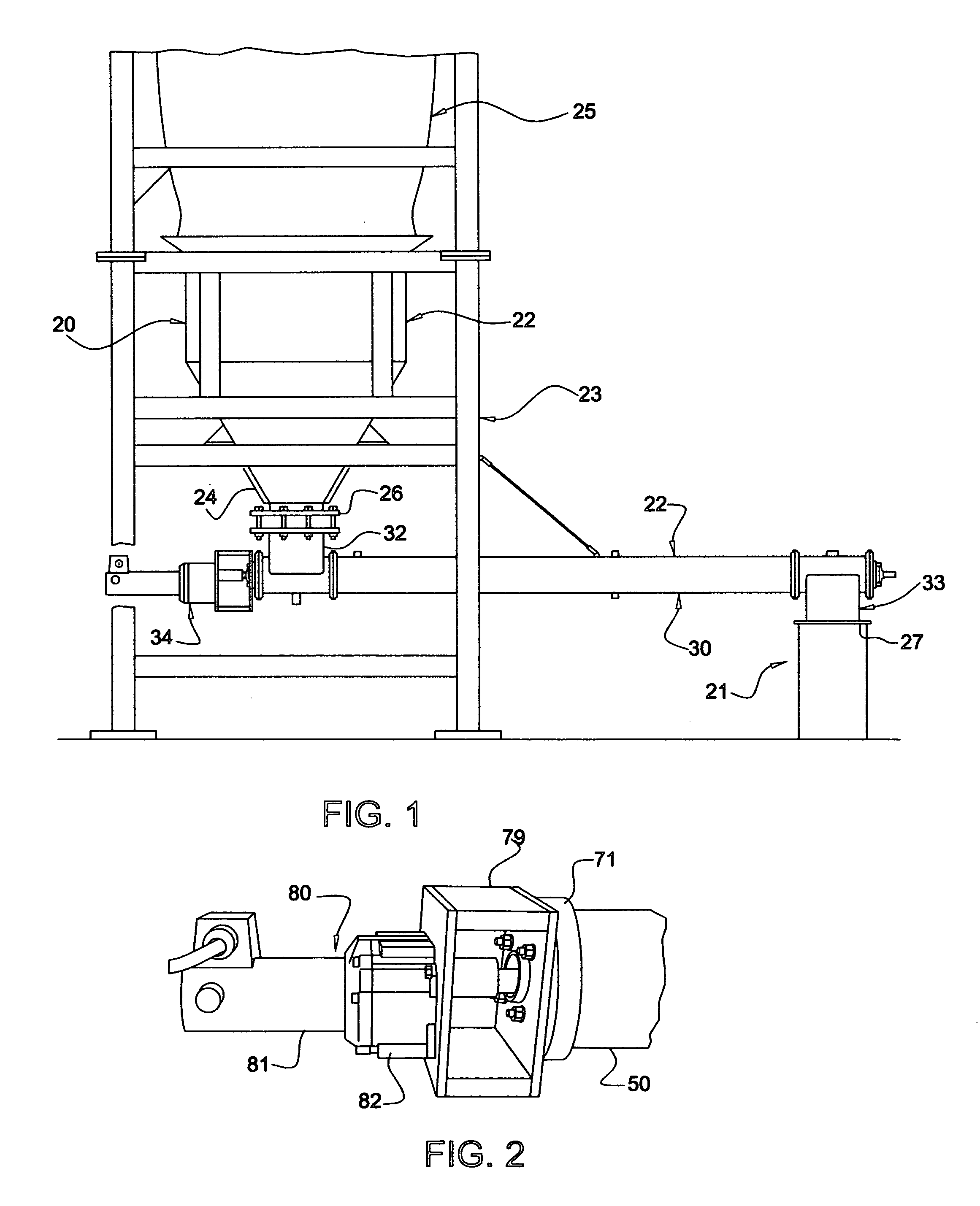
[0014]Referring to FIGS. 1 through 6 of the drawings, there is illustrated a system for conveying a bulk material generally consisting of a hopper 20 for holding a supply of bulk material to be conveyed, a receptacle 21 to which material from the hopper is to be conveyed and a screw conveyor 22 operatively interconnecting the hopper and the receptacle for conveying material from the hopper to the receptacle. Hopper 20 includes an upper, cylindrical section 22 supported on a frame structure 23 and a lower, inverted frusto-concially configured section 24. The upper end of hopper section 22 is open to receive the lower end of a bag 25 having a set of straps at an upper end thereof for suspending the bag from the upper end of the frame structure, and a lower outlet spout through which bulk material contained in the bag may flow into the hopper. The lower end of hopper section 24 is provided with a mating flange 26 for connecting the outlet of the hopper to an inlet of the screw conveyor...


PUM


Abstract

A bulk material handling system generally consisting of means for holding the material; means for conveying the material including a first conduit formed of a permeable material having an inlet communicating with an outlet of the material holding means and an outlet, a second conduit formed of an impermeable material encompassing and spaced from the first conduit, providing a chamber therebetween, and an auger disposed in the first conduit for transporting material received through the inlet to the outlet thereof; means for rotatably driving the auger; and means for supplying a fluidizing gas under pressure to the chamber between the first and second conduits.

Description

[0001]This invention relates to an improved system and method for handling bulk materials, and more particularly to an improved system and method for conveying metered amounts of such materials having poor flowability. The invention further contemplates a novel apparatus for conveying such materials.BACKGROUND OF THE INVENTION[0002]In a number of industries involved in the handling of bulk materials having poor flow characteristics, it commonly has been the practice to convey such materials by means of mechanical conveyors. Typically, such conveyors have consisted of screw conveyors, generally comprising an elongated, rotatable auger housed in an elongated tube. In the use of such conveyors, however, it has been found that the flow rates of sluggish and cohesive bulk materials is poor, the flow rates of such materials are difficult to control, a substantial amount of torque is required to operate such conveyors and such materials tend to build up in the tube around the auger which o...

Claims


Application Information

Patent Timeline
Patent Type & Authority Patents(United States)
IPC IPC(8): B65G53/08
CPCB65G37/00B65G53/20B65G53/48
Inventor AMBS, RICHARD W.
Owner YOUNG INDS
Learn More