Preform precursor for fiber-reinforced composite material, preform for fiber-reinforced composite material, and method of manufacturing the precursor and the preform

a technology of composite materials and precursors, applied in the direction of yarn, transportation and packaging, mechanical equipment, etc., can solve the problems of reducing the degree of design freedom, inevitably heavy aircraft weight, and reducing the weight of aircraft components

Inactive Publication Date: 2006-11-21
SHIKIBO LTD
View PDF7 Cites 26 Cited by
  • Summary
  • Abstract
  • Description
  • Claims
  • Application Information

AI Technical Summary

Benefits of technology

[0014]The portion where the reinforced fibers are disposed in parallel without being formed into a structure along the curved line for bending has a nature that the reinforced fiber resists the bending force. This is because a fiber length of the reinforced fiber disposed in parallel along the curved line and that of the reinforced fiber after bending do not accord with each other. On the other hand, the portion solely constituted of the plurality of reinforced fibers intersecting at a predetermined angle with the reinforced fibers disposed in parallel along the curved line for bending can be easily bent without producing a wrinkle, owing to a variation of an interval between the fibers that takes place without varying the shape along the curved line. This is because the latter portion does not include a fiber provided in a direction that causes resistance against the bending force. By focusing on such nature, it becomes possible to provide a precursor of a preform for a fiber-reinforced composite material that can relatively easily constitute a curved irregular cross-section.
[0018]In case where different strength characteristics are dispersedly designed in a single structural material, a reinforced fiber has to be disposed in accordance with a strength requirement, which can be achieved by partly increasing or decreasing a thickness or a width of the fiber. The third aspect achieves the same effect also by partly varying a diameter of the reinforced fiber to be employed.
[0031]Further, in case where strength in a thickness wise direction is required, for example by a stitching thread, a fibriform thermoplastic resin may be used in combination with the reinforced fiber for constituting a precursor of a preform, and then after appropriately providing a stitch and bending a portion that can be bent a thermo compression bonding may be performed to form a preform for a fiber-reinforced composite material in a desired shape. Such method is also applicable to a preform to be knitted. Such bonding in a thickness wise direction by the stitching, knitting or needle-punching process includes a drilling process of the base material in a thickness wise direction, which contributes in promoting a flow of a resin in a matrix impregnation process for forming a composite material, thereby improving the impregnation efficiency.
[0033]According to this method, since the reinforced fiber along the curved line is not disposed in the portion to be bent along the curved line, it is possible to vary an inner or outer diameter of the portion to be bent along the curved line, and therefore the bending can be easily executed, thus to form a preform for a fiber-reinforced composite material in a desired three-dimensional shape.
[0035]According to such method, since the reinforced fiber is not disposed in parallel along the circular or oval curved line in the portion that can be bent along a circular or oval curved line in a region including a part or a whole of a disk-shape plane or an oval plane, it is possible to vary an inner or outer diameter of the portion to be bent because of a variation of an interval between the fibers, and therefore the bending can be easily executed along the circular or oval curved line, thus to form a preform for a fiber-reinforced composite material in a desired three-dimensional shape.

Problems solved by technology

However, in order to satisfy a strength requirement of an aircraft, a multitude of metal structural members, each of which has a considerable weight, have to be used; therefore a total weight of the aircraft inevitably becomes heavy.
Accordingly, degree of designing freedom is significantly restrained, and in a practical aspect a huge amount of fuel is consumed in each flight; therefore making light-weighted aircraft components has been a critical issue from the viewpoint of manufacturing, operation and safety of an aircraft.

Method used


Image

  • Preform precursor for fiber-reinforced composite material, preform for fiber-reinforced composite material, and method of manufacturing the precursor and the preform
  • Preform precursor for fiber-reinforced composite material, preform for fiber-reinforced composite material, and method of manufacturing the precursor and the preform
  • Preform precursor for fiber-reinforced composite material, preform for fiber-reinforced composite material, and method of manufacturing the precursor and the preform

Examples


Embodiment Construction

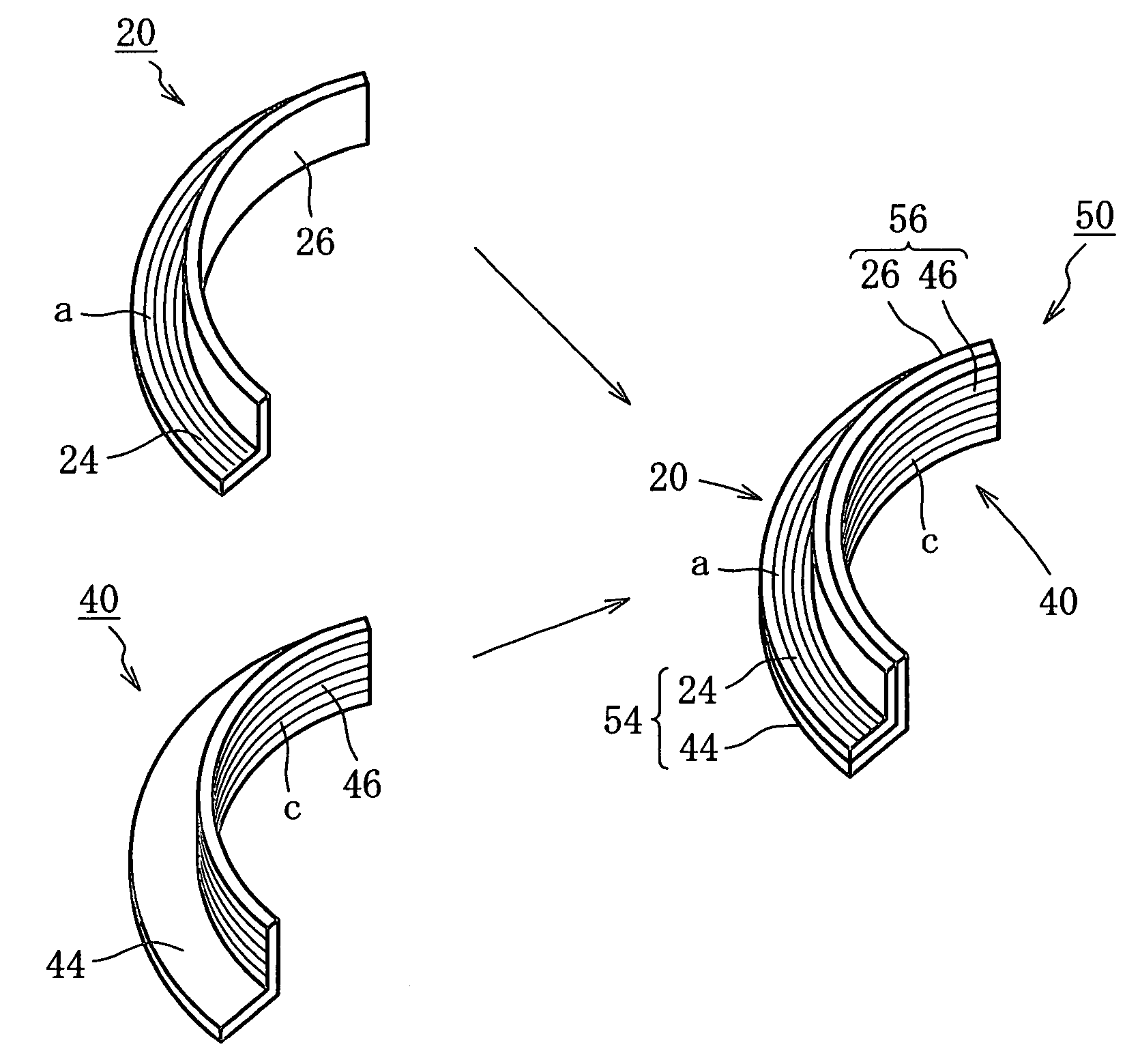
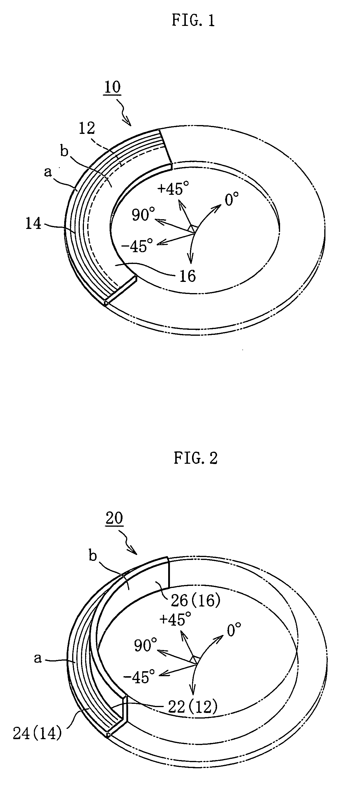
[0044]Hereunder, the best mode for carrying out the present invention will be described referring to the accompanying drawings. FIG. 1 is a perspective view showing a precursor of a preform for a fiber-reinforced composite material 10 having a curved shape in a flat plane, intended for forming a curved preform for a fiber-reinforced composite material having a typical L-shaped irregular cross-section according to an embodiment of the present invention. The curved precursor of a preform for a fiber-reinforced composite material 10 includes an outer circumferential portion 14 and an inner circumferential portion 16 divided by a curved line for bending 12. The outer circumferential portion 14 corresponds to a region a, where a plurality of reinforced fibers is disposed in parallel without being formed into a structure along the curved line for bending 12. The inner circumferential portion 16 corresponds to a section b, where solely another plurality of reinforced fibers is provided, ou...


PUM

PropertyMeasurementUnit
angleaaaaaaaaaa
angleaaaaaaaaaa
angleaaaaaaaaaa

Abstract

A preform for a fiber-reinforced composite material including a bent portion along a curved line for bending, a flange portion corresponding to an outer circumferential portion, and a semi-cylindrical portion formed by bending an inner circumferential portion along the curved line for bending located in a flat plane or a curved plane region. The preform is formed from a precursor having a predetermined extension. The outer circumferential portion corresponds to a first region where a first plurality of reinforced fibers is partially disposed in parallel along the curved line for bending. The inner circumferential portion corresponds to a second region constituted solely of a second plurality of reinforced fibers disposed throughout the entire area, so as to intersect the first plurality of reinforced fibers at a predetermined angle in the first region.

Description

CROSS-REFERENCE TO RELATED APPLICATION[0001]This application is a National Stage entry of International Application Number PCTIJP02 / 08219, filed Aug. 12, 2002. The disclosure of the prior application is hereby incorporated herein in its entirety by reference.TECHNICAL FIELD[0002]The present invention relates to a precursor of a preform for a fiber-reinforced composite material and a preform for a fiber-reinforced composite material formed of a reinforcing fiber, to be used as a structural member that has to have a prescribed strength in an aircraft, an automobile, a vessel, a constructed structure, etc., especially in a circular bore portion or a curved portion such as a wing or a body of an aircraft, and to a method of manufacturing such preform.BACKGROUND ART[0003]Conventionally, metal materials including a particular aluminum alloy, a titanium alloy or a stainless steel have been mainly used as a structural member of an aircraft such as a wing, body, a window frame or a circular ...

Claims


Application Information

Patent Timeline
Patent Type & Authority Patents(United States)
IPC IPC(8): B32B5/12B29B11/16C08J5/04C08L101/00D04H1/46
CPCB29B11/16Y10T428/24074Y10T428/218Y10T156/1043
Inventor SAKONJO, HIDEKIISHIBASHI, MASAYASUTANAMURA, TAKESHIHASHIMOTO, KOICHIHIROKAWA, TETSURO
Owner SHIKIBO LTD
Why Eureka
Try Eureka