LED driving circuit

a driving circuit and light-emitting diode technology, applied in the direction of instruments, light sources, electroluminescent light sources, etc., can solve the problems of further shortening the service life of leds, and achieve the effect of improving voltage transformation efficiency, simple circuit structure, and reducing cos

Inactive Publication Date: 2006-11-21
TOP UNION GLOBALTEK
View PDF7 Cites 102 Cited by
  • Summary
  • Abstract
  • Description
  • Claims
  • Application Information

AI Technical Summary

Benefits of technology

[0009]The main objective of the present invention is to provide an LED driving circuit which can light LEDs and solve the problem of local heat dissipation. Besides, a comparatively simple circuit structure can lower the cost and improve the efficiency of voltage transformation.

Problems solved by technology

The above examples both have a comparatively complex driving circuit; in addition, the heat dissipation is a problem in the complex circuit, which will further shorten the service life of the LEDs.

Method used


Image

  • LED driving circuit
  • LED driving circuit
  • LED driving circuit

Examples


first embodiment

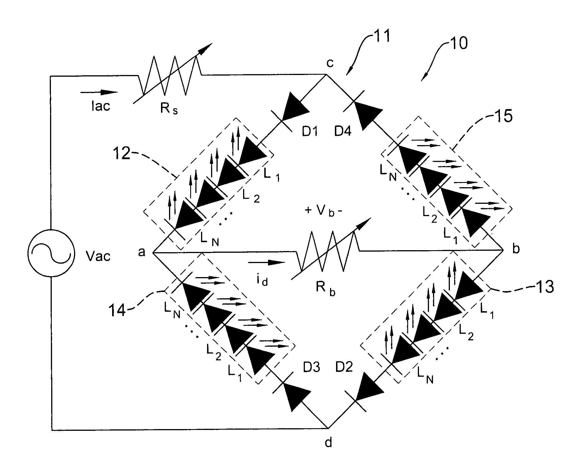
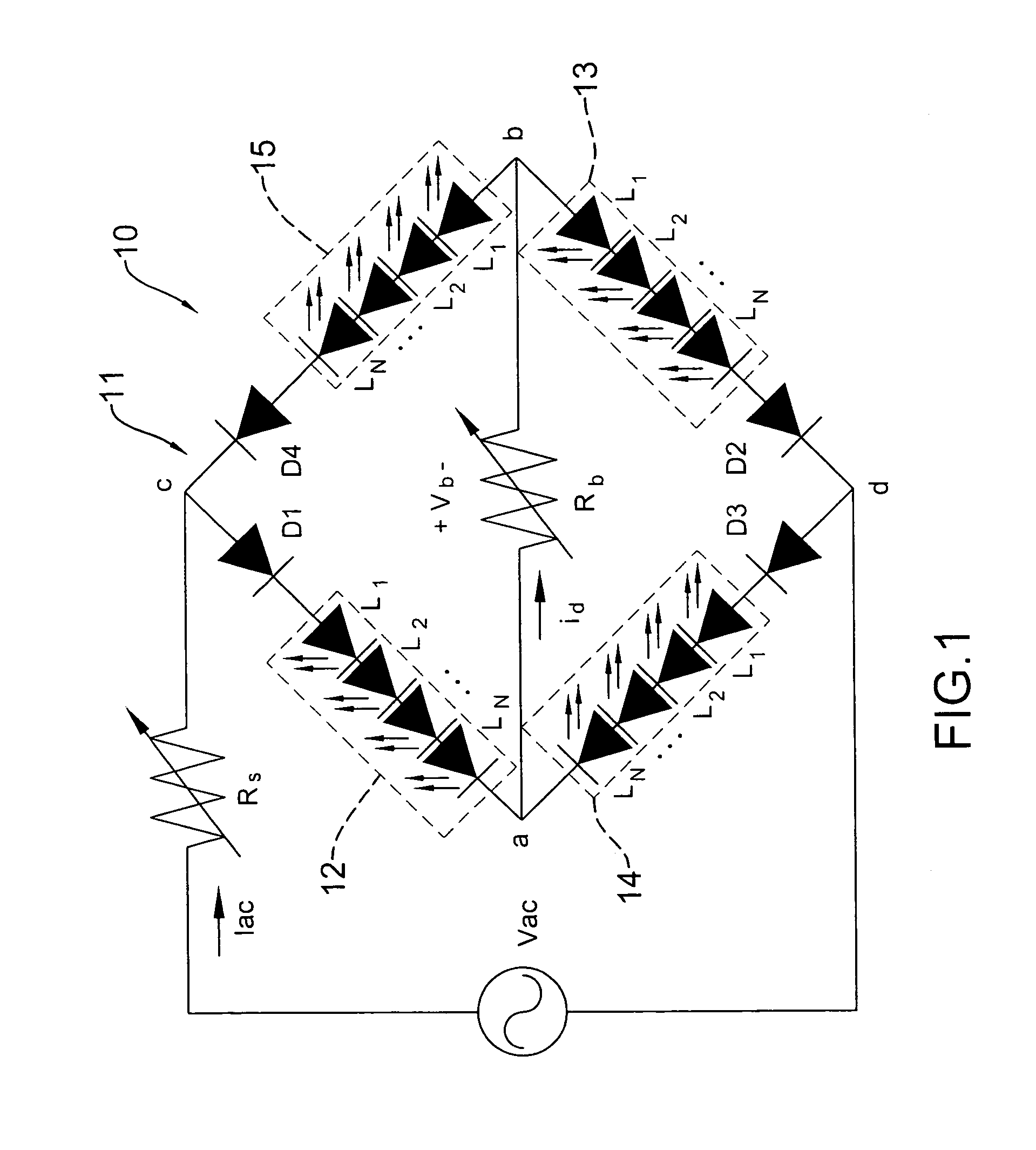
[0016]With reference to FIG. 1, a circuit diagram of an LED driving circuit is disclosed. An LED driving circuit (10) contains a bridge circuit (11) including a first and second pair of opposite branches arranged in a diamond orientation, and forming four junction points (a), (b), (c), (d). A first pair includes a first branch (a) (c) and a second branch (b) (d); a second pair includes a third branch (a) (d), and a fourth branch (b) (c). Four diodes D1, D2, D3 and D4 are respectively located in four branches. A diagonal branch of the bridge is formed between the junction points (a) and (b), and the junction points (c) and (d) are connected to an AC power supply Vac. That is, the bridge circuit (11) is a two-phase circuit, wherein the two pairs of opposite branches respectively serve as a first current loop and a second current loop.

[0017]The current direction in the first current loop is c→a→b→d. The first current loop contains a first and second LED group (12), (13), and each group...

fourth embodiment

[0037]FIG. 5 shows a driving circuit (10c) having multiple bridge circuits (11), the junction point (d) of each bridge circuit (11) is attached to the junction point (c) of the next bridge circuit (11), and the junction point (c) of the first bridge circuit (11) and the junction point (d) of the last bridge circuit (11) is connected to the AC voltage. Two diodes D1 and D4 are connected in reverse direction in the first and fourth branches of the first bridge circuit (11) respectively, and two diodes D2 and D3 are connected in reverse direction in the second and third branches of the last bridge circuit (11). Each bridge circuit (11) has a diagonal branch which has a resistor R connected therein.

[0038]The first branches, the diagonal branch, and the second branches of all bridge circuits (11) form a first current loop, wherein each first branch has a first LED group (12), and each second branch has a second LED group (13).

[0039]The third branches, the diagonal branches, and the fourt...


PUM


Abstract

An LED driving circuit that is directly activated by an AC power supply is disclosed. A driving circuit has a first and second pair of opposite branches. The first pair of opposite branches operates in a positive half cycle of the AC power supply and the second pair of branches operates in a negative half cycle of the AC power supply, so the lighting time for each LED is less than a half cycle time, in other words, the time for heat dissipation is prolonged.

Description

BACKGROUND OF THE INVENTION[0001]1. Field of the Invention[0002]The present invention relates to an LED (light emitting diode) driving circuit, and particularly relates to an LED driving circuit that is capable of activating the LEDs directly by an AC power supply, and the LEDs are arranged in a bridge circuit.[0003]2. Description of Related Art[0004]The LED is developed with advantages of low cost, low power dissipation, and high brightness, which are better than in other illumination devices.[0005]The LED is driven by a DC voltage, so a voltage converter is required to transform an AC voltage to the DC voltage. A common LED driving circuit in prior art has a power supply, a bridge rectifier, a voltage detector and a current direction control circuit, wherein the bridge rectifier is connected to the power supply (AC power supply). The current direction control circuit consists of at least one current control unit, which is further coupled to the LEDs' cathode. The AC voltage is tra...

Claims


Application Information

Patent Timeline
Patent Type & Authority Patents(United States)
IPC IPC(8): H05B37/02
CPCH05B33/0803H05B33/0821H05B45/40
Inventor UANG, CHII-MAWCHEN, WEN-GONG
Owner TOP UNION GLOBALTEK
Why Eureka
Try Eureka