Flip-flop circuit having low power data retention

a flip-flop circuit and low power data technology, applied in the field of integrated circuits, can solve the problems of slowing down the device's operating speed, consuming only leakage power, and becoming more difficult to meet chip leakage targets using traditional power reduction techniques

Active Publication Date: 2006-11-21
NXP USA INC
View PDF5 Cites 38 Cited by
  • Summary
  • Abstract
  • Description
  • Claims
  • Application Information

AI Technical Summary

Problems solved by technology

Most circuits in handheld devices are typically off (e.g., in an idle or deep sleep mode) for a significant portion of time, consuming only leakage power.
As transistor leakage currents increase with finer geometry manufacturing processes, it becomes more difficult to meet chip leakage targets using traditional power reduction techniques.
However, simply increasing the threshold voltage of the transistors may result in unwanted consequences such as slowing the operating speed of the device and limiting circuit performance.
However, in doing so, the state of the circuit block is lost.

Method used


Image

  • Flip-flop circuit having low power data retention
  • Flip-flop circuit having low power data retention
  • Flip-flop circuit having low power data retention

Examples


Embodiment Construction

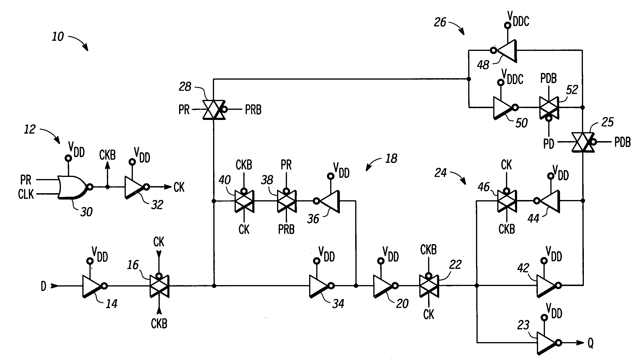
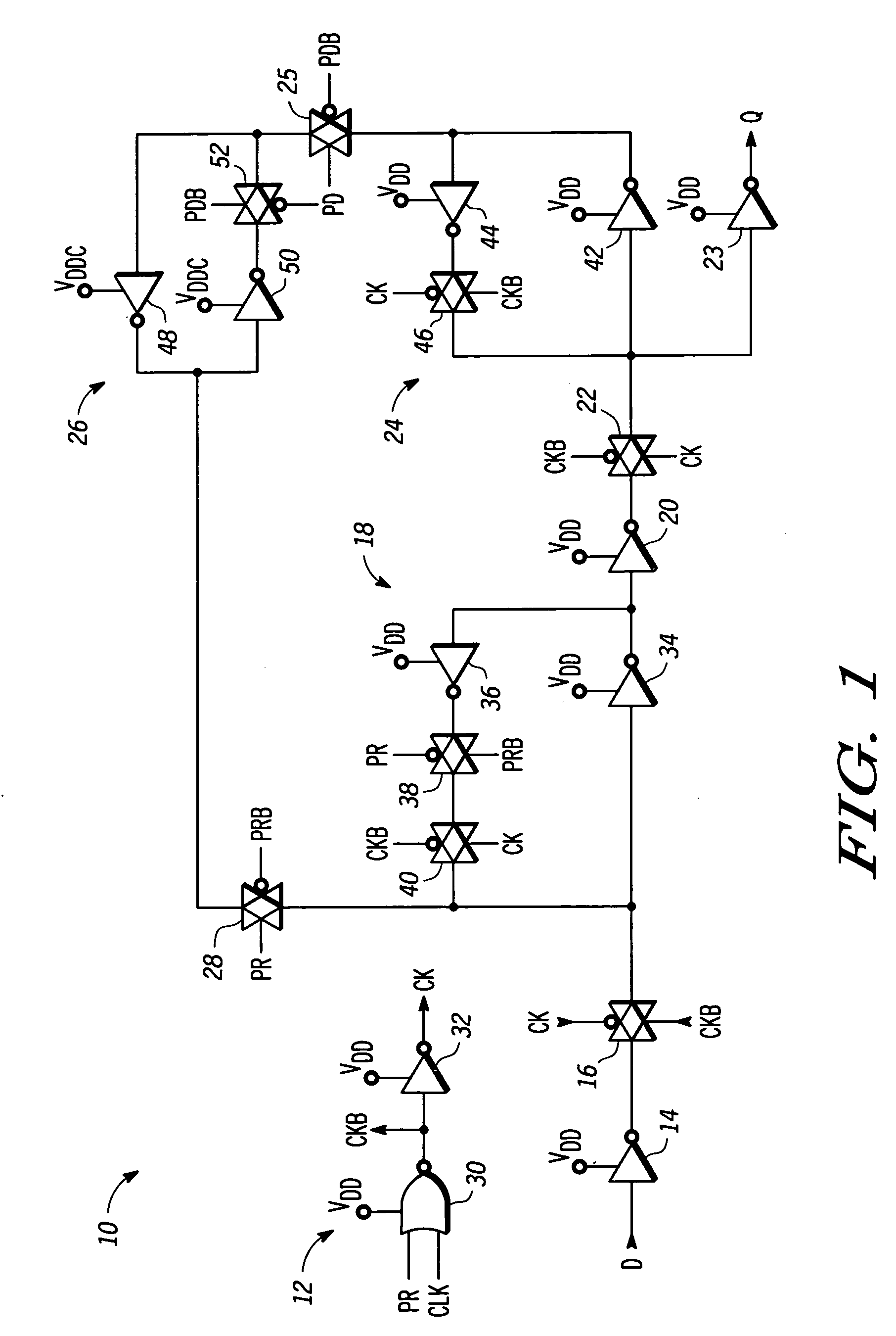
[0011]Generally, in one aspect, the present invention provides a flip-flop circuit that retains its state in a low leakage latch during a low power mode. The flip-flop includes a master latch, a slave latch, and the low-leakage latch. The master and slave latches are coupled to receive a power supply voltage that is removed during the low power mode. The low-leakage latch receives a power supply voltage that is maintained during the low power mode. The master latches latch an input signal during a normal operating mode but are non-functional in response to entering the low power mode.

[0012]The low-leakage latch has an output terminal coupled to the master latch via a transmission gate and an input terminal coupled to the slave latch. The low-leakage latch stores the logic state of a signal that was received from the slave latch during the normal operating mode, and maintains the latched logic state during the low power mode. Power is then removed from the master and slave latches du...


PUM


Abstract

A flip-flop (10) comprises a first latch circuit (18), a second latch circuit (24), and a third latch circuit (26). The first latch circuit (18) is coupled to receive a clock signal and a first power supply voltage. The second latch circuit (24) is coupled to the first latch circuit (18) and receives the clock signal and the first power supply voltage. Preparatory to entering a low power mode, the third latch circuit (26) receives a second power supply voltage and is coupled to the second latch circuit (24) in response to a power down signal. During the low power mode, the first power supply voltage is removed from the first and second latch circuits (18, 24). When returning to a normal operating mode, the first power supply voltage is provided to the first and second latch circuits (18, 24), and the third latch circuit (26) is coupled to the first latch circuit (18) in response to a power restore signal.

Description

RELATED APPLICATION[0001]A related, copending application titled “Flip-Flop Circuit having Low Power Data Retention”, by Padhye et al., Ser. No. 11 / 097,658, is assigned to the assignee hereof, and filed concurrently herewith;[0002]a related, copending application titled “State Retention Within a Data Processing System”, by Padhye et al., Ser. No. 10 / 819,383, filed Apr. 6, 2004, is assigned to the assignee hereof, and filed concurrently herewith; and[0003]a related, copending application titled “State Retention Within a Data Processing System”, by Padhye et al., Ser. No. 10 / 818,861, filed Apr. 6, 2004, is assigned to the assignee hereof, and filed concurrently herewith;FIELD OF THE INVENTION[0004]This invention relates generally to integrated circuits, and more particularly to a flip-flop circuit with low power data retention.RELATED ART[0005]Lower power consumption has been gaining importance in integrated circuit data processing systems due to, for example, wide spread use of porta...

Claims


Application Information

Patent Timeline
Patent Type & Authority Patents(United States)
IPC IPC(8): H03K3/289
CPCH03K3/0375
Inventor PADHYE, MILIND P.YUAN, YUAN A.RASHED, MAHBUB M.
Owner NXP USA INC
Why Eureka
Try Eureka