
Touch-type input apparatus

a technology of input apparatus and input surface, which is applied in the direction of static indicating device, instruments, contacts, etc., can solve the problems of wear on the front surface side resistance plate, deformation, and eventually deformation, and the input operation surface tends to become dirty

Inactive Publication Date: 2006-11-21
SMK CORP
View PDF12 Cites 9 Cited by
  • Summary
  • Abstract
  • Description
  • Claims
  • Application Information

AI Technical Summary

Benefits of technology

[0008]The present invention provides a touch-type input apparatus which is durable, is well-designed, and prevents malfunction.
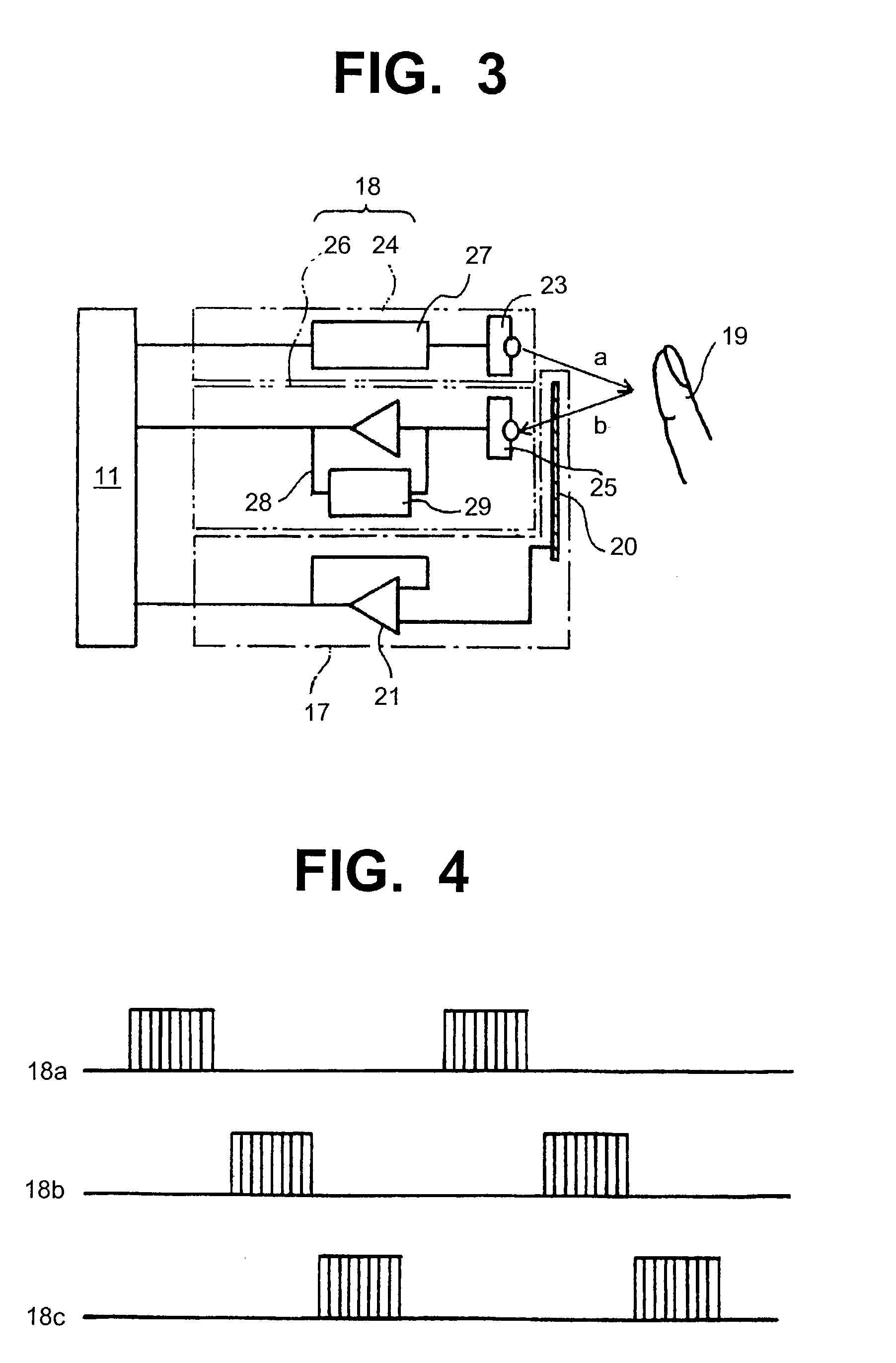
[0010]Using this touch-type input apparatus, it is possible to conduct the input operation by gently touching the touch operation panel. The input operation is detected with detection signals from both of the light detection means and the touch detection means. This apparatus is durable and less subject to malfunction.
[0011]The touch detection means can include a piezoelectric element to detect minute loads on the touch operation panel resulting from the pressure of the touch of a finger or the like on the touch operation panel. Integrating a piezoelectric element into the input apparatus is inexpensive.

Problems solved by technology

This produces wear on the front surface side resistance plate 2 which eventually becomes deformed after repeatedly pressing the tablet sheet 5.
Additionally, since a finger or the like presses on the surface of the front surface side resistance plate 2, the input operation surface tends to become dirty, thereby spoiling its appearance.
However, when the peripheral edge of the exposure window 6a of the protection cover 6 overlaps a movable part of the tablet sheet, such as a part that moves when pressed, a load is imposed on the overlapped part, potentially causing the apparatus to malfunction.
A sufficient boundary must be set for applying pressure, and therefore, there is a limit to reducing the size of the apparatus.

Method used


Image

  • Touch-type input apparatus
  • Touch-type input apparatus
  • Touch-type input apparatus

Examples


Embodiment Construction

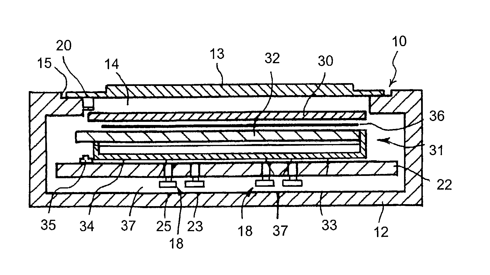
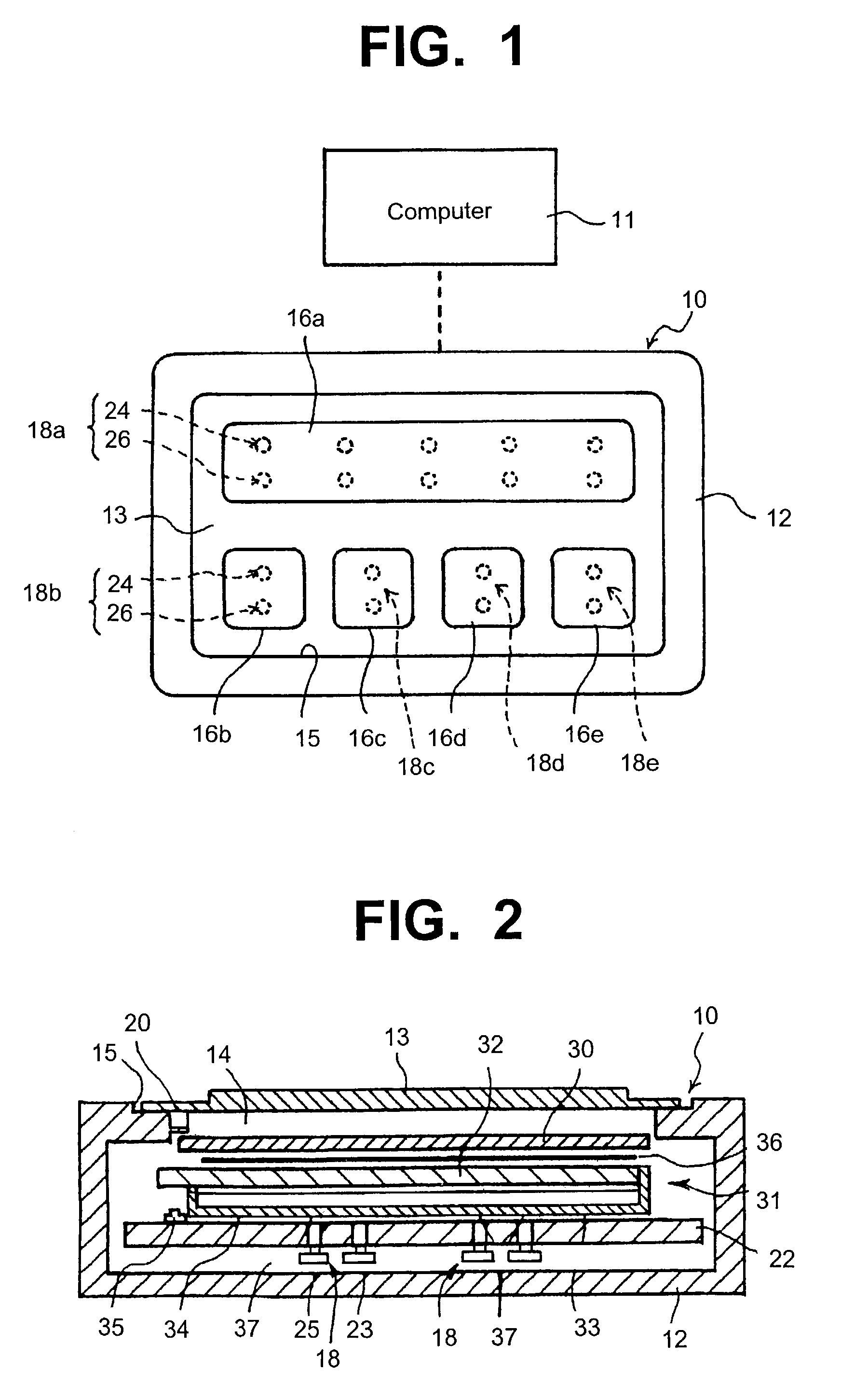
[0019]FIG. 1 is an overview of a touch-type input apparatus. An operation panel 10 is mounted on a home electric appliance such as a washing machine, and a computer 11 controls the appliance. An input operation is conducted on the operation panel 10 in this touch-type input apparatus.

[0020]FIGS. 1 and 2 illustrate that the operation panel 10 includes an outer shell case 12 for forming the external shape of the operation panel 10, a touch operation panel 13 for conducting an input operation from the surface, and detection means for detecting the input operation.

[0021]The outer shell case 12 is formed as a hollow box made of synthetic resin or the like and has an exposure window 14 on the front surface side. An installation recess 15 is formed on the peripheral edge of the opening of the exposure window 14. A touch operation panel 13 fits into the recess 15 and is fixed by welding or the like.

[0022]The touch operation panel 13 is formed from a translucent plate made of a material such...


PUM

PropertyMeasurementUnit
frequencyaaaaaaaaaa
translucentaaaaaaaaaa
structureaaaaaaaaaa

Abstract

A touch-type input apparatus which is used for operating equipment such as electric home appliances, is durable and well-designed, and prevents malfunction is disclosed. The touch-type input apparatus includes a translucent touch operation panel, touch detection means, light detection means, a light reception unit, and input determination means. The touch detection means detects a touch on the touch operation panel. The light detection means includes a light emission unit and a light reception unit. The light emission unit is provided on the rear surface side of the touch operation panel and transmits a unique light signal through the touch operation panel. The light reception unit detects a reflected unique light signal which is transmitted from the light emission unit and is reflected on a front surface side of the touch operation panel. The input determination means determines the intended input operation based on detection signals supplied from the touch detection means and the light detection means.

Description

FIELD OF THE INVENTION[0001]The present invention relates to a touch-type input apparatus used mainly for operating equipment such as electric home appliances.BACKGROUND OF THE INVENTION[0002]Electric home appliances such as water heaters and washing machines are usually provided with an operation input apparatus to operate and control the appliance in an intended way. A press-type input apparatus is a typical operation input apparatus that has a structure as shown in FIG. 5.[0003]The press-type input apparatus 1 includes a tablet sheet 5 which is formed by laminating a pair of resistor plates 2 and 3. The resistor plates 2 and 3 are separated by a slight gap and have uniform resistance layers 2a and 3a formed on the respective surfaces that face each other. This gap between the resistor plates 2 and 3 is created by dot spacers 4 or the like. The tablet sheet 5 is covered partially by a protection cover 6 made of plastic or the like, and the remaining surface of the tablet sheet 5 i...

Claims


Application Information

Patent Timeline
Patent Type & Authority Patents(United States)
IPC IPC(8): G09G5/00G06F3/042G06F3/03G06F3/033G06F3/041G06F3/043H01H13/00H01H13/02H01H13/785H01H13/807H01H35/00H01H36/00
CPCG06F3/03547G06F3/0421G06F3/0433H01H13/785H01H13/807H01H2201/036H01H2223/002H01H2225/002H01H2239/022
Inventor OHTSUKA, KENJI
Owner SMK CORP
Learn More