Long term rapid color changing time indicator

a color changing time and indicator technology, applied in the field of time indicators, can solve problems such as difficulty in distinguishing a clear endpoint, and achieve the effect of eliminating problems

Inactive Publication Date: 2006-11-21
BRADY WORLDWIDE INC
View PDF22 Cites 38 Cited by
  • Summary
  • Abstract
  • Description
  • Claims
  • Application Information

AI Technical Summary

Benefits of technology

[0016]It is therefore an advantage of the present invention to provide a long term time indicator wherein the dye does not begin to appear until the end or near the end of the time interval.
[0017]It is another advantage of the present invention to provide a time indicator that remains unchanged (white or clear) until near the end of the time interval, and then the color rapidly or instantaneously appears.
[0018]It is yet another advantage of the present invention to provide a time indicator that acts as a time switch with a color-appearing step-function from white to dark to clearly show that a time interval has ended.
[0019]It is still another advantage of the present invention to provide a time indicator that utilizes separate timing control and color change mechanisms to eliminate the problems associated with gradual color change in longer term time indicating devices.
[0020]These and other features, aspects, and advantages of the present invention will become better understood upon consideration of the following detailed description, drawings, and appended claims.

Problems solved by technology

Very problematic are prior indicators of long periods wherein the timing process is as long as the color change process, making it difficult to distinguish a clear endpoint.

Method used


Image

  • Long term rapid color changing time indicator
  • Long term rapid color changing time indicator
  • Long term rapid color changing time indicator

Examples


example

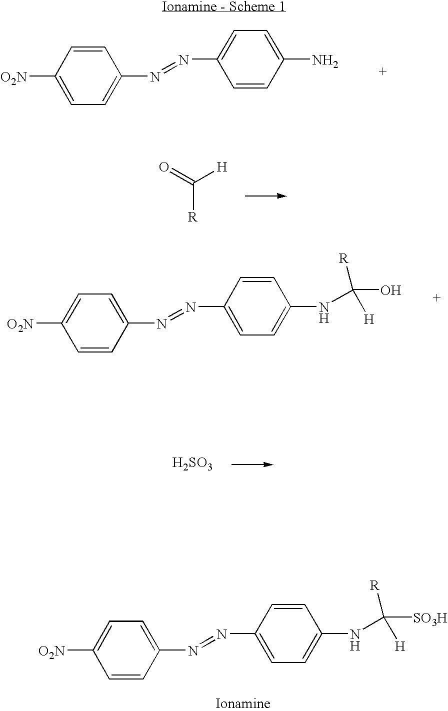
[0043]It has been demonstrated that a long term time indicator would be possible using the transformation of a non-migrating dye to a migrating dye brought about by migration of an amine. Fast migrating Disperse Orange 3 was chemically modified as follows to a non-migratory dye. In a two neck round bottom flask (300 ml.) equipped with magnetic stir bar, reflux condenser, thermometer and a stirrer / heating mantle, were mixed equimolar amounts (0.02 to 0.05 moles) of Disperse Orange 3 dye (available from Aldrich, 95% dye) and formaldehyde / sodium bisulfite 1:1 adduct (available from Aldrich) in 200 ml. of 50% aqueous alcohol (distilled water and completely denatured alcohol (ethanol / methanol {100 parts}, 2-propanol {10 parts}, methyl isobutyl ketone {1 part}). The mixture was stirred and heated to reflux for approximately six hours, then left to cool to room temperature overnight. The copious reddish brown precipitate was filtered using a Buchner funnel and vacuum sidearm flask. The cru...


PUM

PropertyMeasurementUnit
thickaaaaaaaaaa
timeaaaaaaaaaa
time indicatoraaaaaaaaaa

Abstract

A long term rapid color changing time indicator includes a front part and a back part. The front part includes a transparent layer, an opaque layer, a colorant layer, and a neutralizing layer. The colorant layer includes a matrix and a colorant having a non-migratory form that does not migrate in the matrix and having a migratory form that migrates in the matrix. The back part has a reactant. When the front part and the back part are placed in contact, the reactant migrates into the neutralizing layer and a portion of the reactant is depleted by a coreactant. The unreacted reactant migrates into the colorant layer and reacts with the non-migratory form of the colorant converting the non-migratory form to the migratory form such that the migratory form of the colorant migrates through the opaque layer to cause a visual color indication in the transparent layer.

Description

CROSS-REFERENCES TO RELATED APPLICATIONS[0001]Not Applicable.STATEMENT REGARDING FEDERALLY SPONSORED RESEARCH[0002]Not Applicable.BACKGROUND OF THE INVENTION[0003]1. Field of the Invention[0004]This invention relates to a time indicator and, in particular, to a long term time indicator which provides a rapid and clear indication of expiration.[0005]2. Description of the Related Art[0006]Numerous devices are known which provide, after activation, a visual indication of the passage of a predetermined amount of time. Such a time indicator is useful, for example, as a security badge, as an indicator of the length of time a perishable item has been on the wholesaler's or retailer's shelf and for numerous other uses.[0007]Some known time-indicating devices involve the migration of a colorant, dye or other material through a media. Many of these known time indicators, which are generally short term time indicators, are based on the migration of ink from one substrate through another substr...

Claims


Application Information

Patent Timeline
Patent Type & Authority Patents(United States)
IPC IPC(8): G04B17/00G01N31/22G04F1/00G04F1/06G04F13/06
CPCG04F1/06G04F13/06
Inventor HAAS, DAVID J.HOLT, ROBERT J.DAVIS, LEONARD H.
Owner BRADY WORLDWIDE INC
Why Eureka
Try Eureka