Optical techniques for examination of biological tissue

a biological tissue and optical technique technology, applied in the field of biological tissue examination and imaging, can solve the problems of inapplicability of certain aspects of cross-sectional imaging techniques, and none of those techniques have fully satisfied all needs in tissue examination

Inactive Publication Date: 2006-11-21
NONINVASIVE TECH
View PDF42 Cites 74 Cited by
  • Summary
  • Abstract
  • Description
  • Claims
  • Application Information

AI Technical Summary

Benefits of technology

[0040]The modulation frequency of the introduced radiation has a value that enables resolution of the phase shift that originates during migration of photons in the subject.

Problems solved by technology

However, with lower energy radiation, such as visible or infra-red radiation, the radiation is strongly scattered and absorbed in biological tissue, and the migration path cannot be approximated by a straight line, making inapplicable certain aspects of cross-sectional imaging techniques.
None of those techniques have fully satisfied all needs in tissue examination.

Method used


Image

  • Optical techniques for examination of biological tissue
  • Optical techniques for examination of biological tissue
  • Optical techniques for examination of biological tissue

Examples


Embodiment Construction

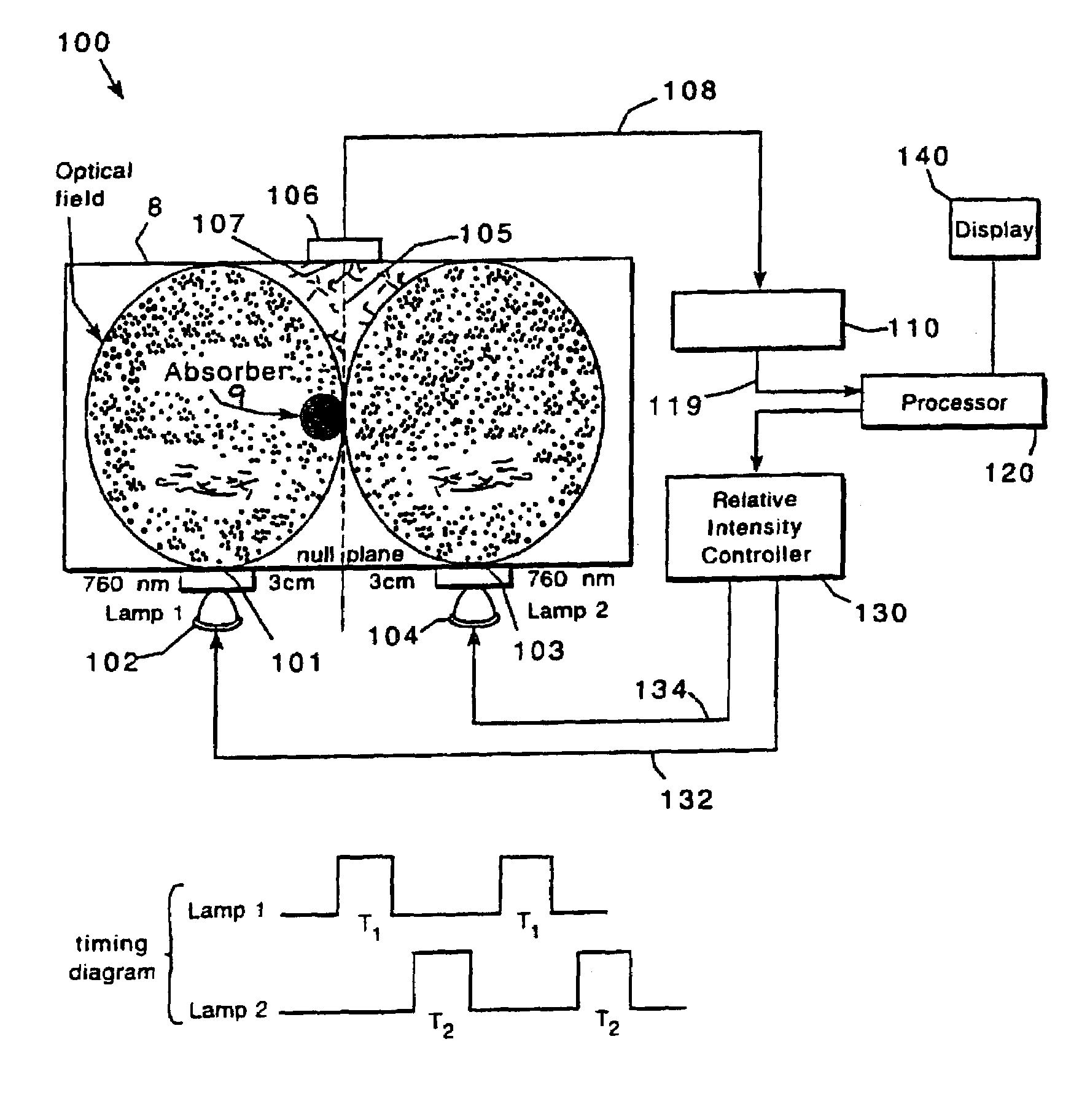
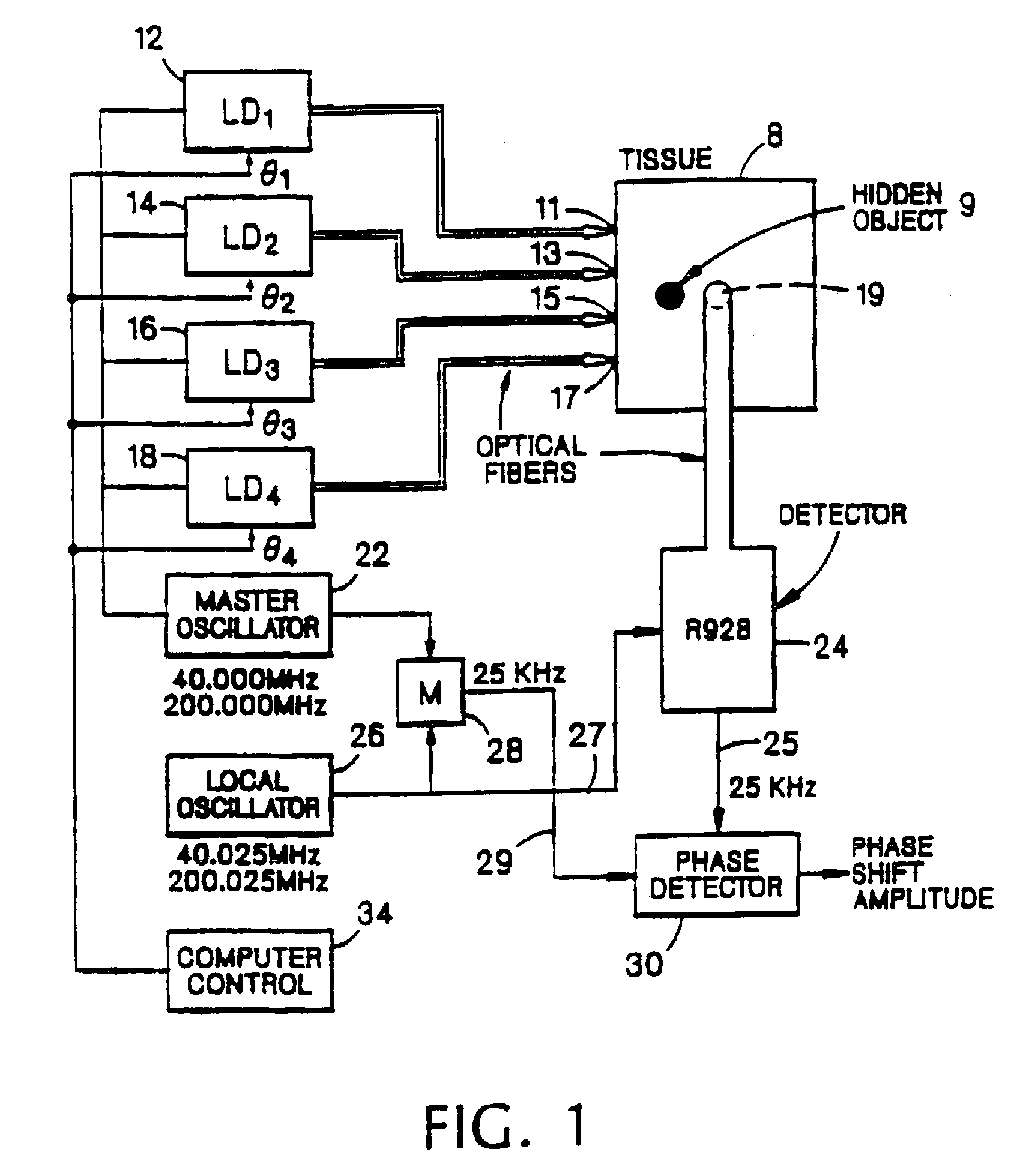
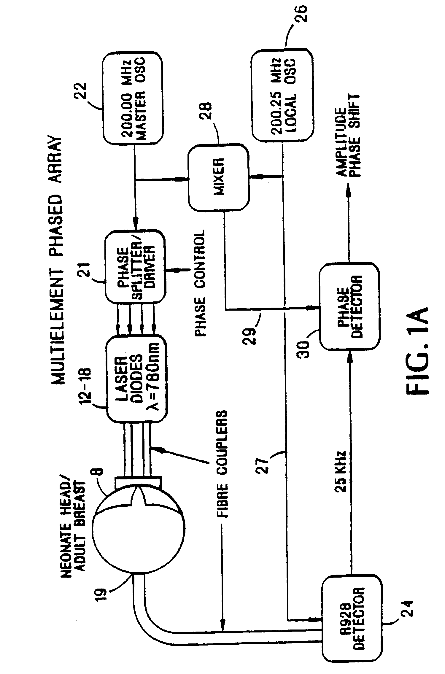
[0069]Imaging system embodiments of the present invention based upon interference effects of radiation migrating in a subject having scattering and absorptive properties are shown in FIGS. 1, 2, and 3. The systems effectively utilize, in this scattering medium, a directional beam of visible or IR radiation generated and / or detected by an array of sources and / or detectors, respectively. For instance, in the case of an array of sources, each source is placed at a selected location in the array and emits intensity modulated radiation, preferably coherent radiation from a laser diode, of a selected intensity and phase. The criteria for selecting the source locations, the intensities, and the phases of the respective sources is the shape of the desired beam that at any time point possesses a substantial photon density gradient produced by interference effects of radiation from the various sources. This gradient of photon density is localized and has directional properties. Overall, the r...


PUM

PropertyMeasurementUnit
wavelengthaaaaaaaaaa
voltageaaaaaaaaaa
frequenciesaaaaaaaaaa

Abstract

Methods and systems are described that examine tissue positioned between input ports and a detection port. At lease one source of a visible or infrared wavelength is provided that introduces electromagnetic radiation into the subject. The detection port is optically coupled to a detector that is connected to a detector circuit. Radiation intensities are selected for introduction at the input ports to define a null plane in the tissue. The detection port is positioned relative to the null plane. Radiation is introduced into the subject at the first input port and the radiation that migrates through the tissue is detected. The detector circuit stores a first detector signal corresponding to the first detected radiation. Radiation is introduced at the second input port and is detected. The first detector signal is subtracted from a second detector signal corresponding to the second detected radiation to obtain processed data.

Description

[0001]This application is a continuation of U.S. application 09 / 561,656, filed on May 2, 2000, which is a continuation of U.S. application Ser. No. 09 / 170,833, filed on Oct. 13, 1998, now U.S. Pat. No. 6,058,324, which is a continuation of U.S. application Ser. No. 08 / 849,202 filed on Jun. 2, 1997, now U.S. Pat. No. 5,820,558, which is a continuation of PCT Application PCT / US 95 / 15694, filed on Dec. 4, 1995, which is a continuation-in-part of U.S. application Ser. No. 08 / 349,018, filed on Dec. 2, 1994, now U.S. Pat. No. 5,673,701.BACKGROUND OF THE INVENTION [0002]This invention relates to examination and imaging of biological tissue using visible or infra-red radiation.[0003]Traditionally, potentially harmful ionizing radiation (for example, X-ray or γ-ray) has been used to image biological tissue. This radiation propagates in the tissue on straight, ballistic tracks, i.e., scattering of the radiation is negligible. Thus, imaging is based on evaluation of the absorption levels of di...

Claims


Application Information

Patent Timeline
Patent Type & Authority Patents(United States)
IPC IPC(8): A61B5/00G01N21/47
CPCA61B5/0073A61B5/0091A61B5/1455A61B5/14553A61B5/4312A61B5/6814G01N21/3151G01N21/4795G01N21/49G01N21/6456A61B5/14551A61B2562/0233A61B2562/0242A61B2562/043A61B2562/146G01N21/47G01N2021/1789G01N2021/3181G01N2021/6421G01N2021/6484G01N2201/0696
Inventor CHANCE, BRITTON
Owner NONINVASIVE TECH
Why Eureka
Try Eureka