Technique for synchronizing network devices in an access data network

Inactive Publication Date: 2006-11-21
CISCO TECH INC
View PDF8 Cites 65 Cited by
  • Summary
  • Abstract
  • Description
  • Claims
  • Application Information

AI Technical Summary

Problems solved by technology

For networks that use a shared access medium to communicate between subscribers and the service provider (e.g., cable networks, wireless networks, etc.), providing reliable high-quality voice/video communication over such networks is not an easy task.
Typically, the use of RF modulated optical si

Method used


Image

  • Technique for synchronizing network devices in an access data network
  • Technique for synchronizing network devices in an access data network
  • Technique for synchronizing network devices in an access data network

Examples


Embodiment Construction

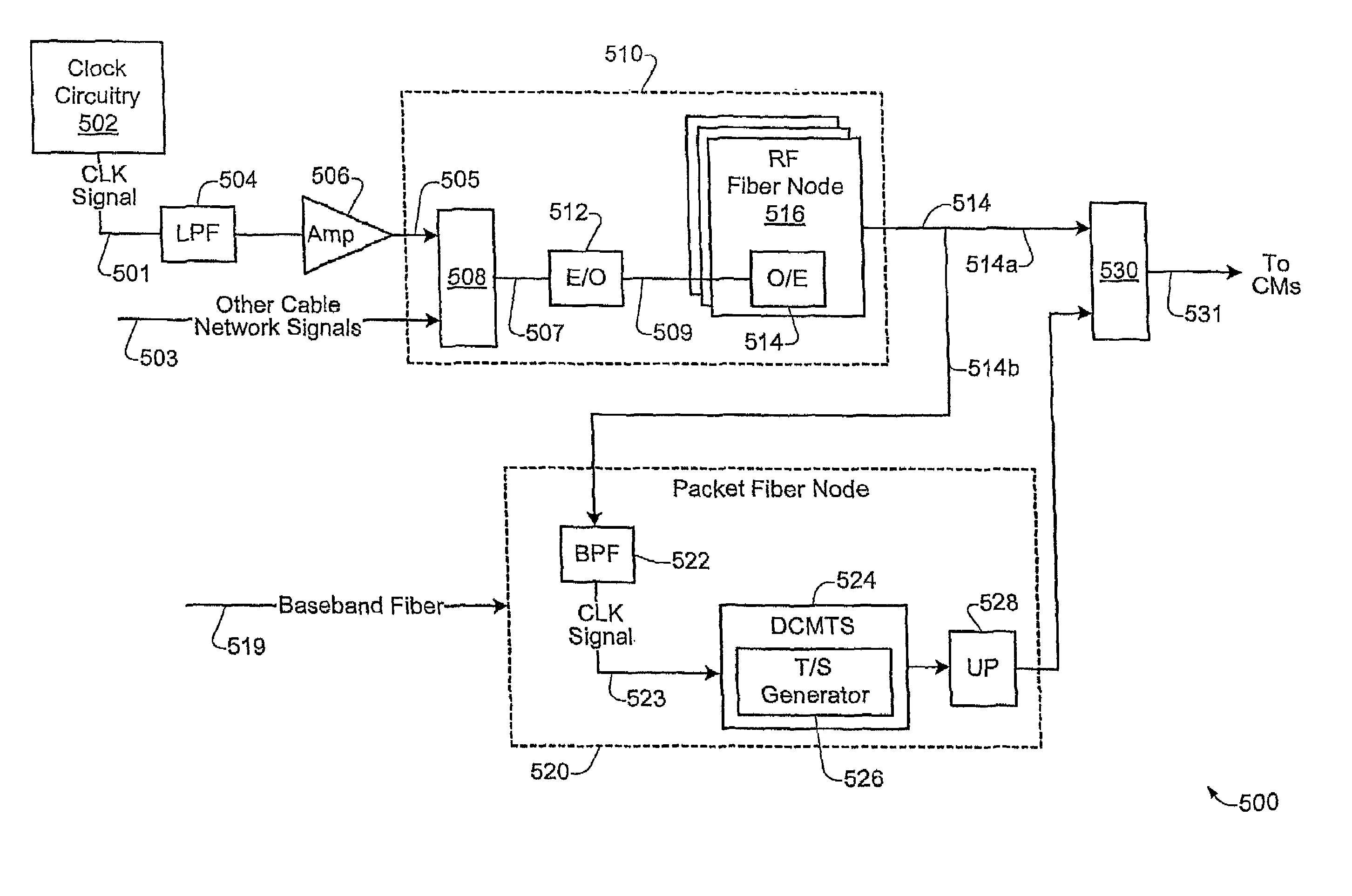
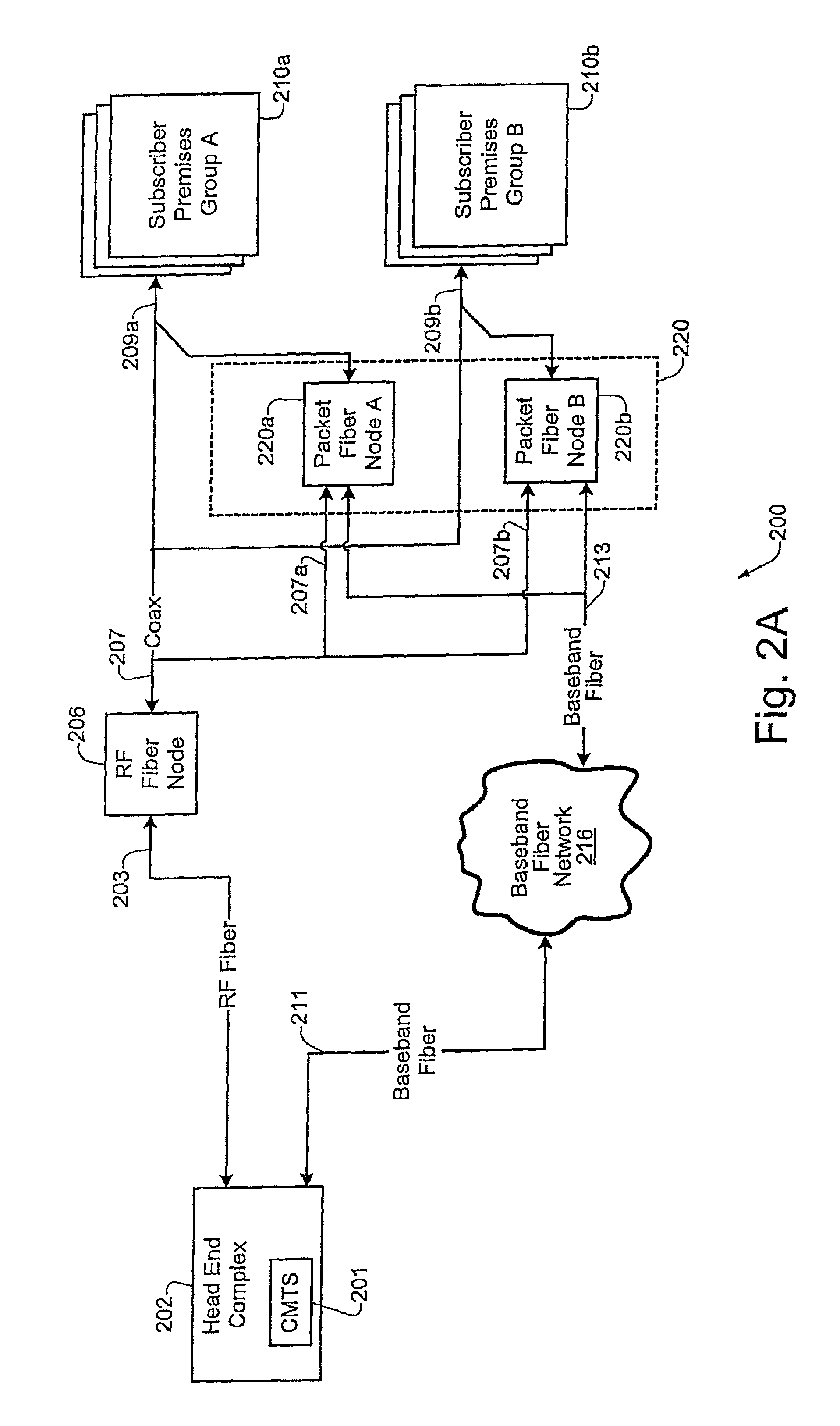
[0027]FIGS. 2A and 2B illustrate specific embodiments of cable networks which may be used for implementing the synchronization technique of the present invention. In the embodiment of FIG. 2A, the Head End complex 202 includes a centralized CMTS device 201 which may be configured to implement DOCSIS functionality. A specific embodiment of the CMTS 201 is described in greater detail below with respect to FIGS. 7 and 8 of the drawings.

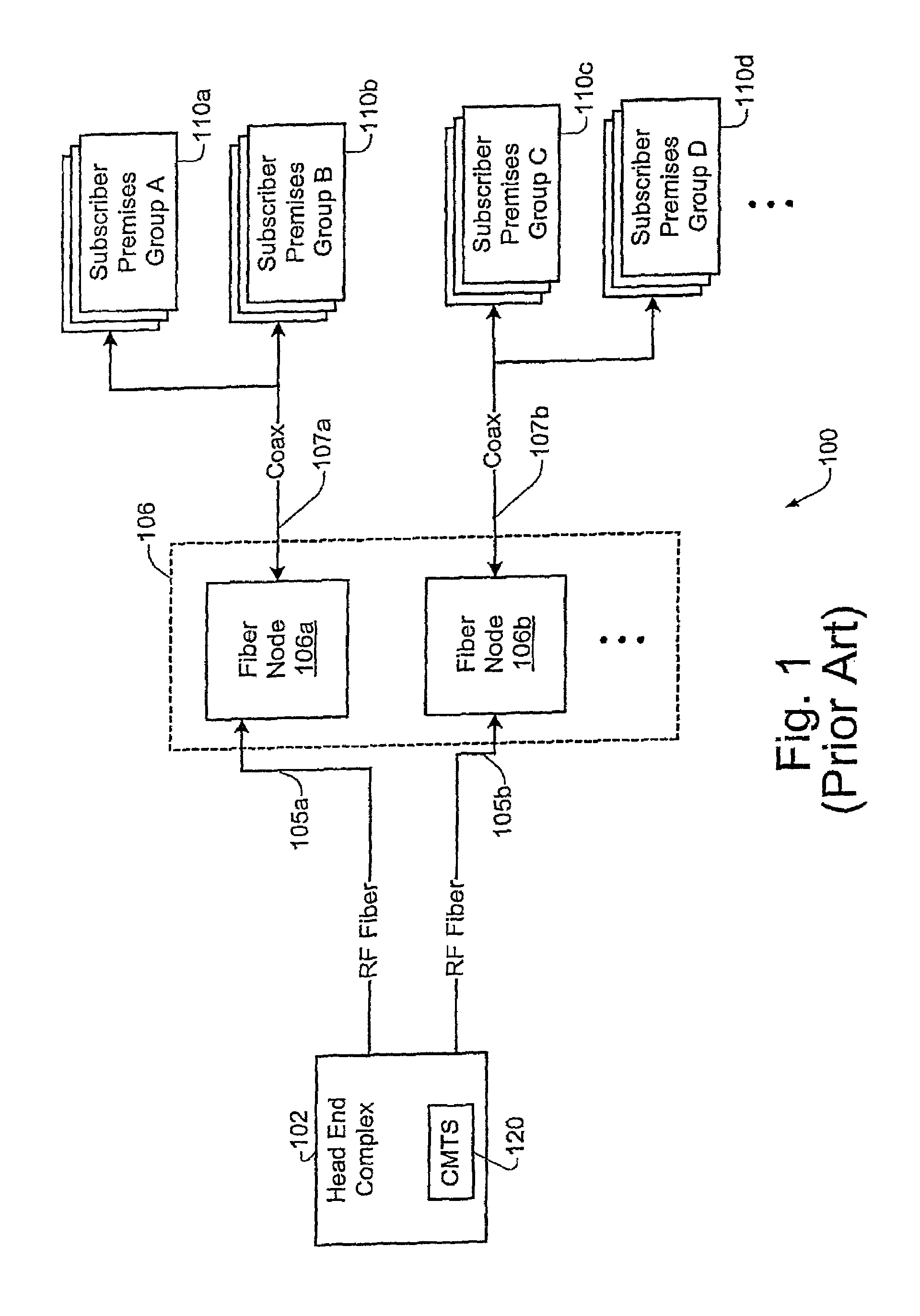
[0028]As show in FIG. 2A, the cable network 200 includes two different types of fiber nodes, namely RF fiber nodes (e.g. 206), and packet fiber nodes (e.g. 220a, 220b). According to a specific embodiment, the RF fiber node 206 may be configured as a conventional fiber node such as fiber nodes 106 of FIG. 1. According to a specific implementation, the RF fiber node 206 may be configured to handle all legacy RF downstream and upstream communications (such as, for example, set-top box signals, telemetry signals, etc., and communications which occur on centr...


PUM


Abstract

A master clock reference signal may be provided to selected packet fiber nodes in order to synchronize the local clock reference signals generated at selected devices in a cable network. In this way, selected portions of the cable network may be synchronized to a common timing reference signal. Additionally, synchronized timestamp information may also be provided to selected network devices in order to achieve synchronization of timestamps across a selected portion of the cable network.

Description

RELATED APPLICATION DATA[0001]The present application is related to U.S. patent application Ser. No. 09 / 490,761, filed on Jan. 24, 2000, and U.S. patent application Ser. No. 09 / 606,503, filed Jun. 28, 2000, which claims priority under 35 USC 119(e) from U.S. Provisional Patent Application Ser. No. 60 / 159,085, filed on Oct. 13, 1999. The present application is also related to U.S. patent application Ser. No. 09 / 894,958, filed concurrently herewith, naming John Chapman as inventor. Each of these applications is incorporated herein by reference in its entirety for all purposes.BACKGROUND OF THE INVENTION[0002]The present invention relates to digital computer network technology. More specifically, it relates to a technique for synchronizing network devices in an access data network.[0003]Broadband access technologies such as cable, fiber optic, and wireless have made rapid progress in recent years. Recently there has been a convergence of voice and data networks which is due in part to ...

Claims


Application Information

Patent Timeline
IPC IPC(8): G06F1/04
CPCH04J3/0664H04L12/2801H04N7/17309H04N21/242H04N21/6168H04J3/0641
Inventor CHAPMAN, JOHN T.CROCKER, DANIEL W.
Owner CISCO TECH INC
Why Eureka
Try Eureka