Method and apparatus to establish safe state in a volatile computer memory under multiple hardware and software malfunction conditions

a volatile memory and safe state technology, applied in the field of storage of data in the memory of a computer system, to achieve the effect of improving the ability to place volatile memory in the safe state and preventing data loss

Active Publication Date: 2006-11-21
NETWORK APPLIANCE INC
View PDF6 Cites 68 Cited by
  • Summary
  • Abstract
  • Description
  • Claims
  • Application Information

AI Technical Summary

Benefits of technology

[0012]The invention involves monitoring the status of key elements and functions of a computer system to detect the vast majority of common malfunction or error conditions, and in response, placing volatile memory into a safe state to prevent data loss upon the occurrence of the error condition. Monitoring the status of the a few key elements and functions consolidates, channels or funnels all of the major error conditions into a single safe-state enable response which is used to reliably place in the volatile memory into the safe or self-refresh state. Thereafter and depending on the error condition, the volatile memory may be connected to an auxiliary uninterruptible battery backup power source to maintain the data written in the volatile memory. The ability to place the volatile memory in the safe state is improved by selecting the key elements and functions of the computer elements to monitor and then converting indications of their status into a single response which places the volatile memory in the safe state. A complex variety of error conditions are channeled, consolidated and funneled into a single response which enables the safe-state of volatile memory in complex computer systems.

Problems solved by technology

The volatile memory may also be powered from an auxiliary uninterruptible power supply in response to these conditions.
Another error condition which places the volatile memory into the safe state is a cessation in executing software instructions by a CPU of the computer system.

Method used


Image

  • Method and apparatus to establish safe state in a volatile computer memory under multiple hardware and software malfunction conditions
  • Method and apparatus to establish safe state in a volatile computer memory under multiple hardware and software malfunction conditions
  • Method and apparatus to establish safe state in a volatile computer memory under multiple hardware and software malfunction conditions

Examples


Embodiment Construction

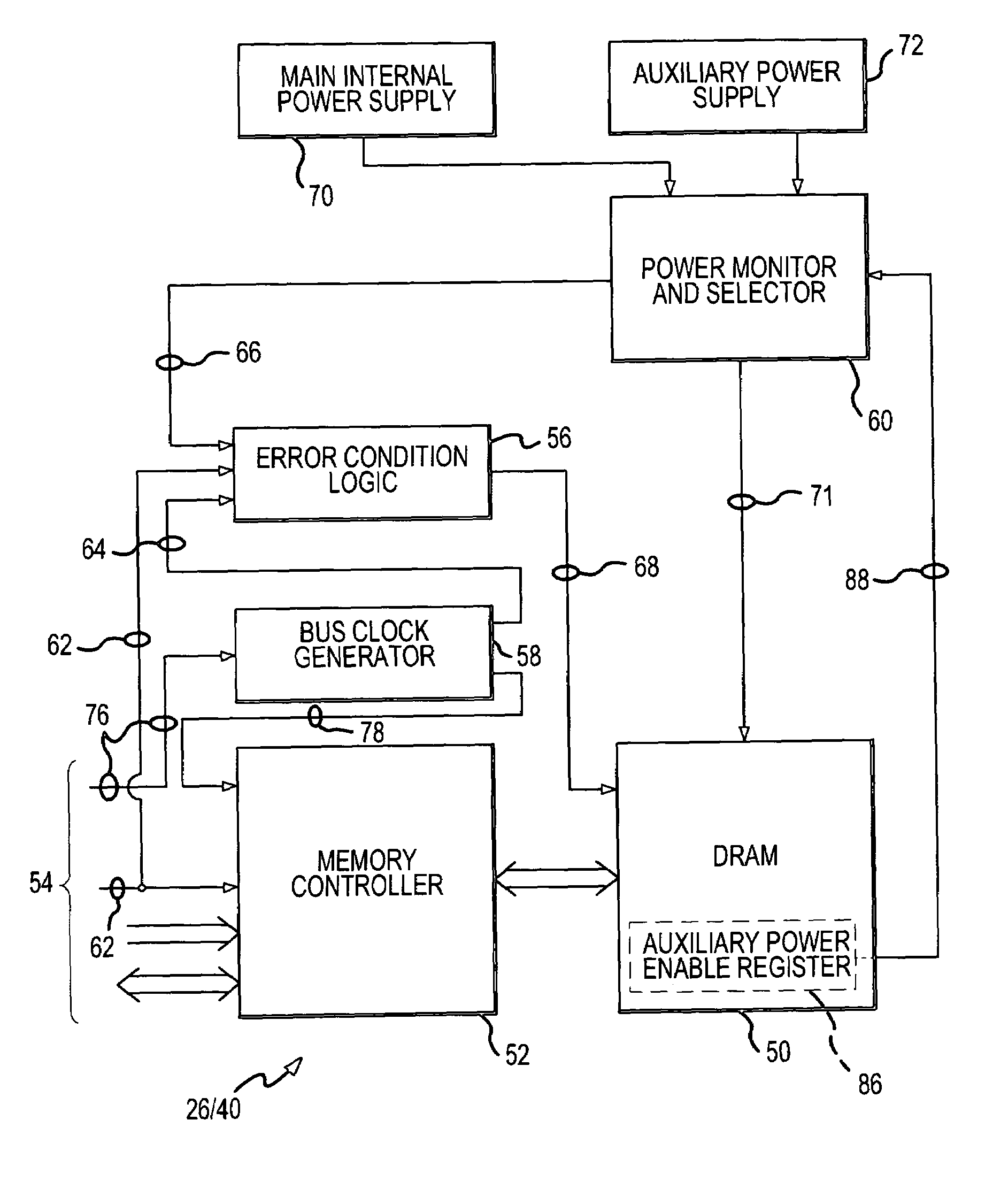
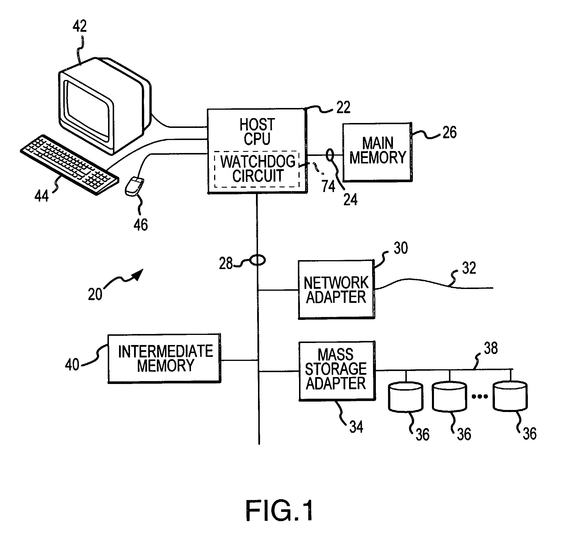
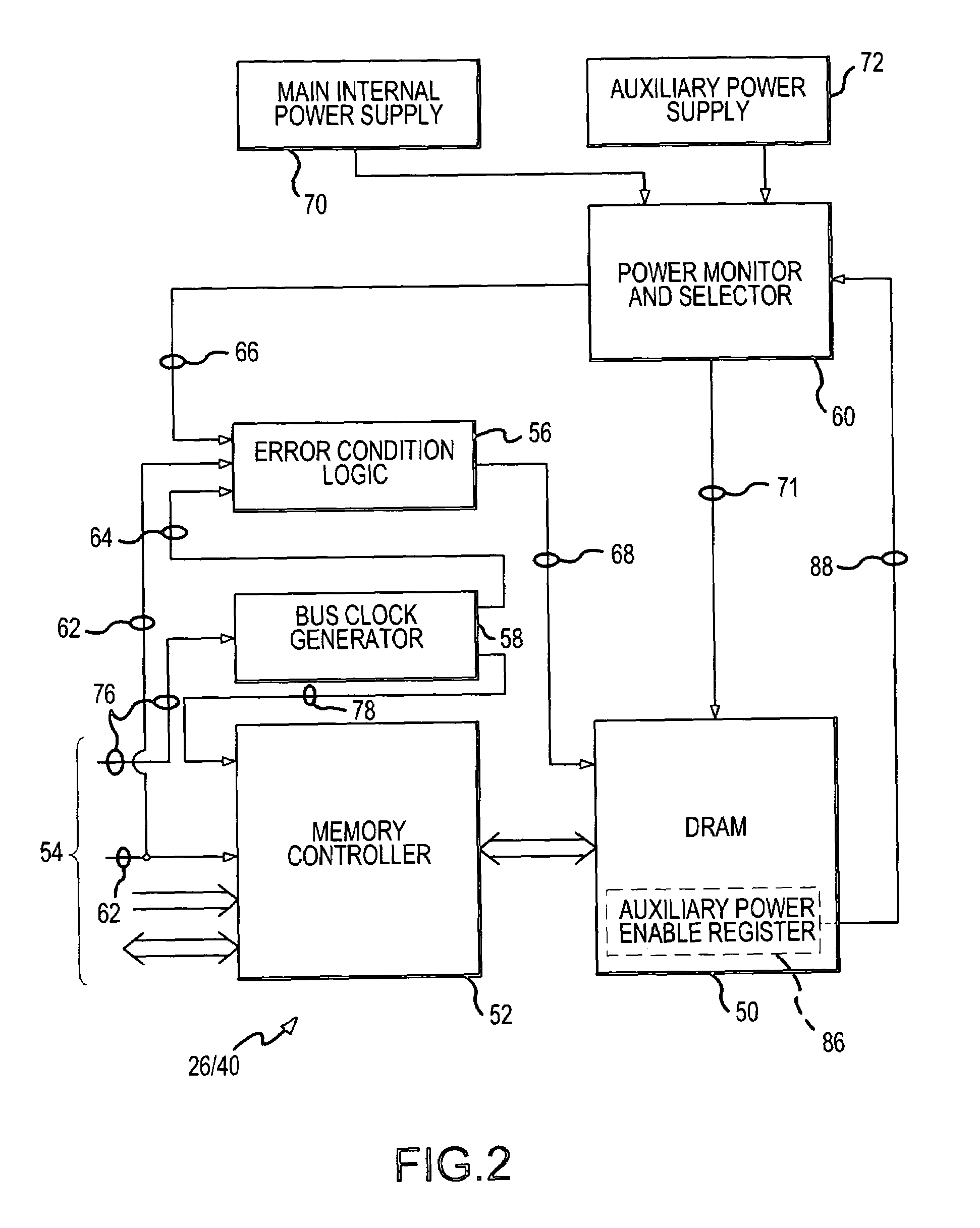
[0030]The present invention relates to consolidating, channeling or funneling the major conditions which could lead to or create loss of data in a volatile memory of a computer system into a single response or enable signal which places memory components into a safe state to prevent data loss. Typically, the memories which are susceptible to data loss are volatile. Volatile memory does not inherently and permanently retain the data which is written to or recorded in it, but instead requires some type of continually applied action to maintain that data. The most common form of volatile memory is dynamic random access memory (DRAM). To retain the data in a DRAM, the individual data-retaining memory cells (typically capacitors) must be periodically refreshed or electrically recharged to maintain the electrical charge condition which represents the data. If not periodically refreshed, the electrical condition or charge dissipates, resulting in the loss of the data.

[0031]The most typical...


PUM


Abstract

Volatile memory is placed into a data-preserving safe state in a computer system in response to any one of a reduction in power applied to the volatile memory, a bus reset signal on a data communication bus of the computer system, and an absence of a bus clock signal on the bus. The volatile memory is powered from an auxiliary uninterruptible power supply in response to the reduction in power. The volatile memory is also placed into the data-preserving safe state in response to a cessation in executing software instructions by a CPU of the computer system. Placing the volatile memory into the safe state in response to and under these conditions enhances the opportunity to preserve data in response to error and malfunction conditions.

Description

CROSS-REFERENCE TO RELATED APPLICATION[0001]This invention and application are related to the following other invention: “Conversion Card and Method to Convert a General Purpose Personal Computer into a Dedicated Mass Storage Appliance,” described in U.S. application Ser. No. 10 / 219,375. This application is filed concurrently herewith by some of the present inventors and is assigned to the assignee of the present invention. The disclosure of this related application is incorporated herein by this reference.FIELD OF THE INVENTION[0002]This invention relates to the storage of data in a memory of a computer system, and more particularly to a new and improved method and apparatus which effectively responds to the most common malfunction or error conditions to place volatile memory of the computer into a safe or self-refresh state, thereby preventing loss of the data as a result of the error conditions. The error conditions include a termination of functionality (a “crash”) of the hardwa...

Claims


Application Information

Patent Timeline
Patent Type & Authority Patents(United States)
IPC IPC(8): G06F11/00G11C11/406G11C11/4072
CPCG11C11/406G11C11/40611G11C11/4072
Inventor KILBOURNE, ALLENREGER, BRAD A.VALIN, STEVE
Owner NETWORK APPLIANCE INC
Why Eureka
Try Eureka