Rod pulling and pushing machine for pipe bursting

a technology of pulling and pushing machine and pipe bursting, which is applied in the direction of mechanical equipment, pipe laying and repair, sewer pipelines, etc., can solve the problems of large bearing capacity, large bearing capacity, and inability to pass through the collapsed section of the rod string or winch rop

Active Publication Date: 2006-11-28
CHARLES MACHINE WORKS
View PDF20 Cites 7 Cited by
  • Summary
  • Abstract
  • Description
  • Claims
  • Application Information

AI Technical Summary

Benefits of technology

[0013]It is advantageous but not necessary to preload the shaft against the roller bearing when no load is applied to the rod string. This preload can be modest, in the 500 to 2000 lb range. It is best achieved with a preloaded spring, the spring is depressed a short percentage of its design travel in the installed condition. This preload does not change as axial thrust in the payout direction is applied. As axial thrust in the pullback direction is applied, the modest spring force is overcome and the spring compresses further. This allows axial movement of the shaft relative to the bearings. As the shaft moves through the short distance per the design, it soon contacts the plain bearing load flange.
[0017]In order to overcome these potential problems with residual load, a vise of the invention is configured to grip the rod string and provide frictional force due to high hydraulically induced clamping forces. In addition to the frictional force, should the residual loads be exceptionally high, the gripping jaws are configured to encounter a shoulder on the rod after a brief amount of axial slippage. This slippage is best kept to a minimum, preferably in the range of 0.10 to 0.25 inch, in order to limit damage to the gripped surfaces on the rod and jaw.
[0022]Conventional cylinders as described above with a rod extending through one end of the cylinder have forces that are not equal in the extension and retraction directions. The area of the cylinder bore is always greater than the area of the cylinder bore less the cross sectional area of the rod. This is well understood in hydraulic cylinder application and allows the design of the cylinder to be tailored with variation in rod size should the retraction direction not be the primary work direction. A larger rod diameter causes the rod side of the cylinder to have a small area and therefore permits rapid retraction for a given hydraulic pump flow rate. A bursting machine using the concepts disclosed herein uses the more powerful extension direction to pull rod back, and the less powerful direction to thrust rod in the payout direction. The cylinders each have a rod that is large in comparison to the cylinder size, thus there is no compromise on performance of the machine due to either using cylinders in the ‘wrong’ direction, or using cylinders available through an industrial catalog that would have a small rod diameter.
[0024]The combination of the relatively large rod diameter coupled with the desire not to feed the hydraulic cylinders through flexible hoses that move with the bodies creates an opportunity to feed the cylinders through drilled longitudinal passages in the rod. The hydraulic hoses are attached to the rod at the rod end which is anchored to the frame or shore plate. These dual passages are drilled the length of the rod to provide both ingress and egress of the hydraulic fluid to the cylinder cavities. These passages eliminate any need for the hoses to move with the carriage.
[0028]For the aforementioned reason, the cradle of the invention is preferably designed in not only a telescoping manner, but is also engineered to follow a path during retraction that would cause it to move away from the rod as it is retracted. This distance gained between the cradle and the rod helps prevent the rod upset from hanging up on the cradle as the relative axial movement occurs. Any entanglement between the cradle and rod could result in a damaged cradle mechanism.

Problems solved by technology

In many applications where an existing line has collapsed, the rod string or winch rope cannot be passed through the collapsed section successfully.
Roller bearings of this capacity are moderately but not excessively large and costly.
Bearings of this capacity are very large and costly.
This bearing will not support rotation during pullback and will in fact cause the rotation motor to stall should rotation be attempted when high axial pullback forces are applied.

Method used


Image

  • Rod pulling and pushing machine for pipe bursting
  • Rod pulling and pushing machine for pipe bursting
  • Rod pulling and pushing machine for pipe bursting

Examples


Embodiment Construction

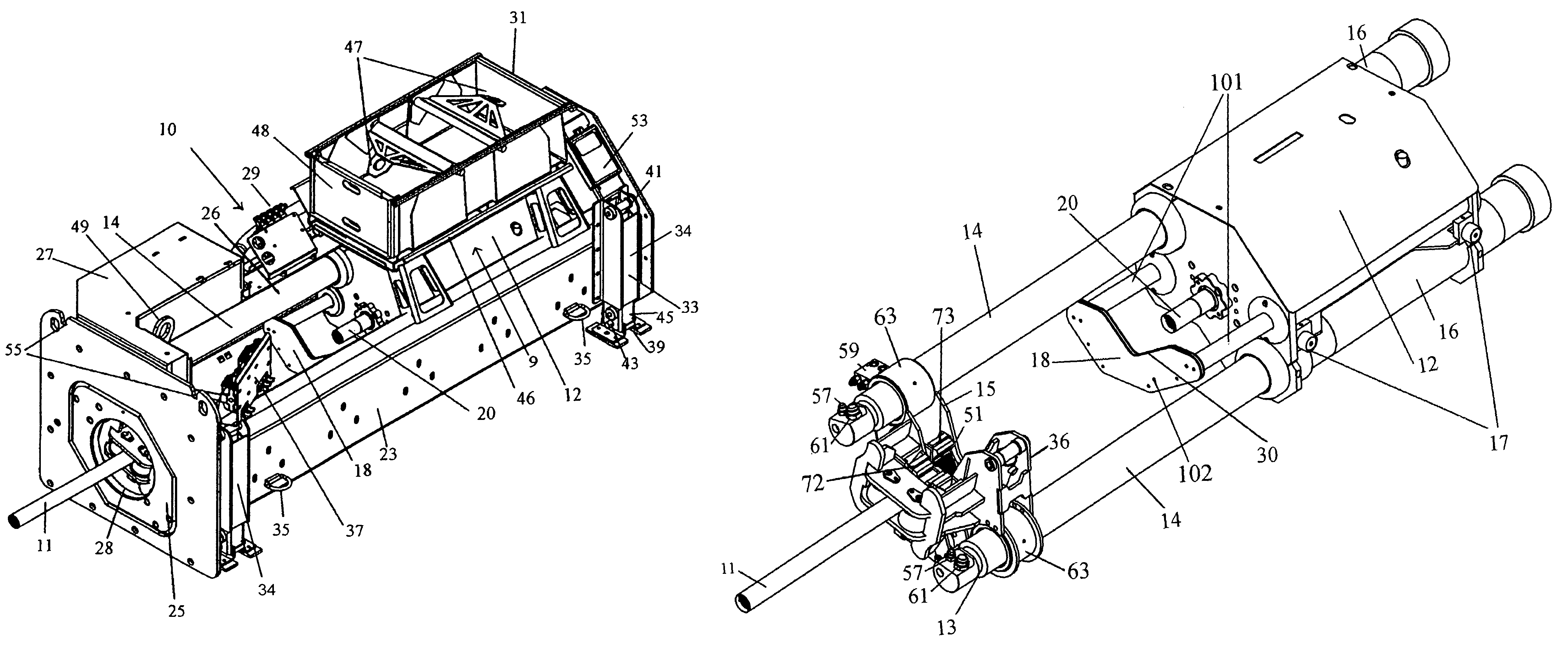
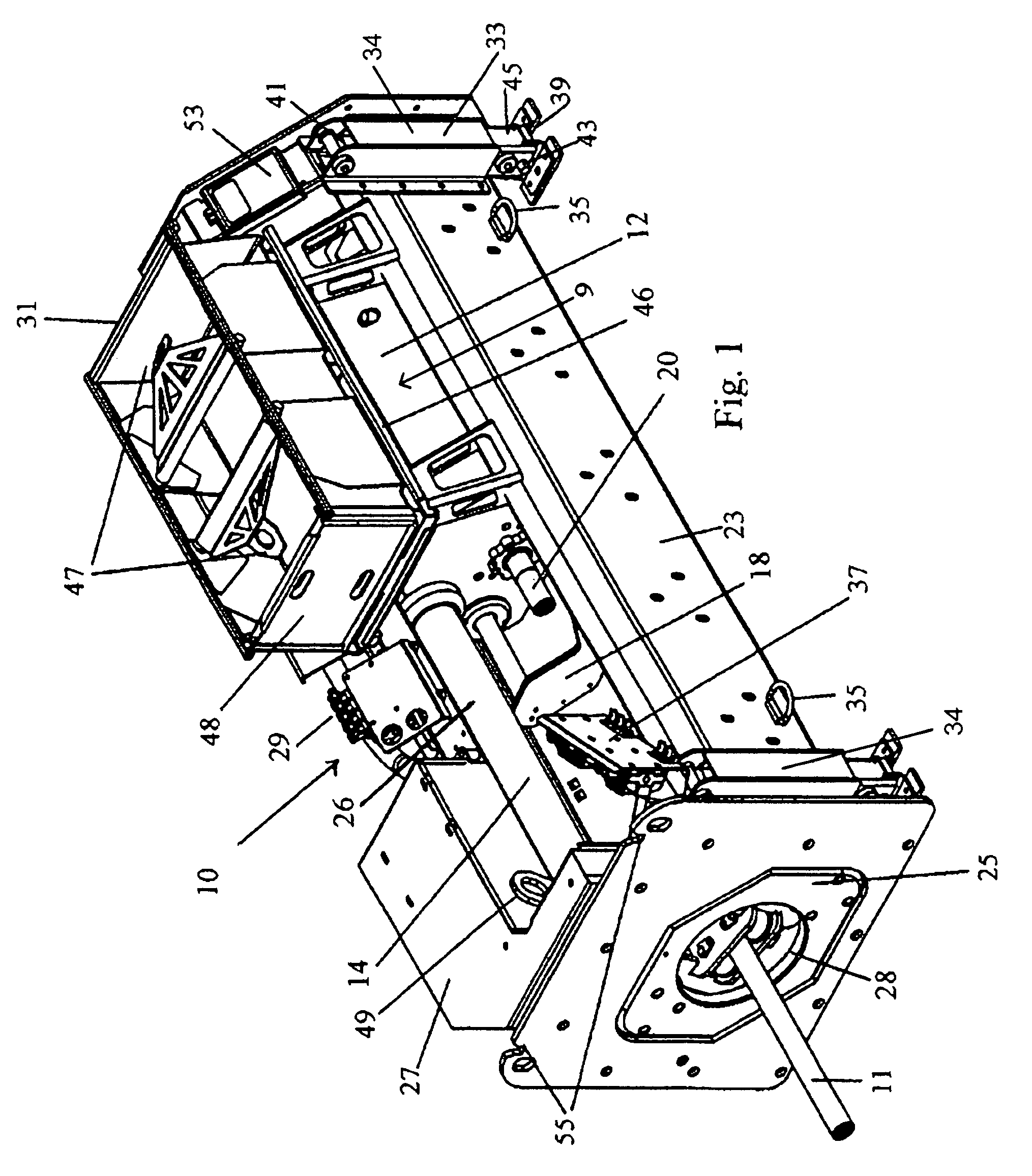
[0056]FIG. 1 shows a downhole machine 10 of a pipe bursting machine of the invention. A spindle assembly 9 including a spindle frame 12 is shown with its sheet metal cover in place. Spindle frame 12 traverses right-to-left a distance equal to 40% of the overall length of the entire machine. The spindle shaft 115 of spindle assembly 9 is connected to a rod string 11 by a threaded joint in the end of a spindle shaft extension 20 which is made as a separate part for ease of replaceability.

[0057]Force to perform the pipe bursting operation is applied to spindle frame 12 via a pair of hydraulic cylinders 26. A cylinder rod 14 of each cylinder 26 is attached to a front shore plate 25. Shore plate 25 is placed against the access pit wall and the face of the existing or host pipe. A rod box 31 stores rods to add to or remove from rod string 11. When rod box 31 is full, tabs 47 are rotated upwards and a lifting hook is engaged. Box 31 is then replaced with a box full of rods or an empty box,...


PUM


Abstract

A rod pushing and pulling machine includes at least one hydraulic cylinder having a front end thereof engagable with a reaction surface at an entry opening of a existing pipeline or borehole, a spindle assembly, and a dual vise assembly. The spindle assembly includes a frame, a spindle shaft rotatably mounted in the frame, a distal end of the spindle shaft being threaded for engagement with a mating thread of a rod, a drive system for rotating the spindle shaft in threading and unthreading directions, the spindle frame being secured to a rear end of the hydraulic cylinder for pushing or pulling of a rod string engaged to the spindle shaft upon extension or retraction of the hydraulic cylinder, and a support assembly for the spindle shaft. The support assembly includes a set of roller bearings rotatably supporting the spindle shaft, a radial flange on the spindle shaft, and a load flange secured to the spindle frame positioned to engage the radial flange, whereby the radial flange comes into engagement with the load flange during pulling operation to prevent rotation of the spindle shaft during pulling operation, and leaves engagement with the load flange during pushing operation so that the spindle shaft may rotate during pushing operation supported by the roller bearings. The dual vise assembly has two pairs of separately actuable jaws positioned to grip a rod nearest the spindle shaft and a rod adjacent the rod nearest the spindle shaft.

Description

TECHNICAL FIELD[0001]The invention relates to underground pipe bursting and replacement systems of the static type which operate by pushing or pulling a string of rods to which a bursting head or other tooling is attached.BACKGROUND OF THE INVENTION[0002]Pipe bursting is a well known process that brings enormous potential for the efficient and unobtrusive replacement of buried pipelines. Currently the there are two widely used but separate systems used to accomplish pipe bursting. The choice of the system is most often dependent on the type of utility being upgraded.[0003]Gravity sanitary sewer systems are made up of interconnected pipes buried at depths from (4) to (40) foot beneath the surface. These systems make use of ‘manholes’ to provide access for maintenance and cleaning of the interiors of the pipes. It is advantageous to minimize the damage and potential need for replacement of these manholes during the bursting operation. To do that requires practicing the method describe...

Claims


Application Information

Patent Timeline
Patent Type & Authority Patents(United States)
IPC IPC(8): F16L1/028
CPCE21B7/205F16L55/1658
Inventor WENTWORTH, STEVEN W.CRANE, ROBERT F.
Owner CHARLES MACHINE WORKS
Why Eureka
Try Eureka