Methods of minimally invasive unicompartmental knee replacement

a knee replacement and unicompartmental technology, applied in the field of knee replacement procedures, can solve the problems of difficult to achieve reproducible clinical results, relatively large incisions with significant exposure, and the traditional unicompartmental knee replacement technique is very technically demanding, so as to facilitate the preparation of the proximal tibia, facilitate the application of a tibial cutting guide and/or a tibial stylus, and promote reproducible and accurate bone preparation

Inactive Publication Date: 2006-11-28
MICROPORT ORTHOPEDICS HLDG INC
View PDF49 Cites 390 Cited by
  • Summary
  • Abstract
  • Description
  • Claims
  • Application Information

AI Technical Summary

Benefits of technology

[0025]Still another object of the present invention is to simplify and facilitate application of a tibial cutting guide and/or tibial stylus in small incision unicompartmental knee replacement procedures.
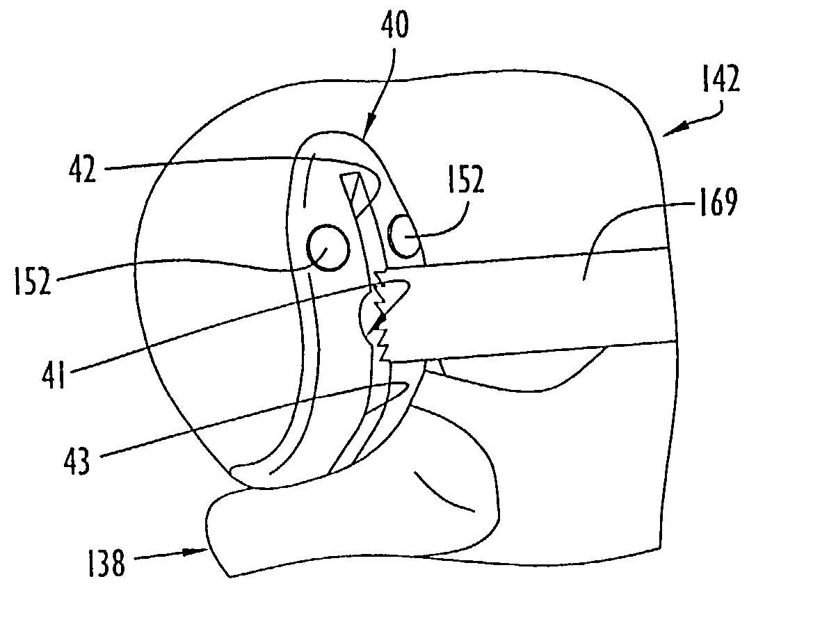
[0026]Yet a further object of the present invention is to facilitate preparation of the proximal tibia to receive a posterior tibial fixation peg within the confines of a small incision in unicompartmental knee replacement procedures.
[0027]It is another object of the present invention to promote reproducible, accurate bone preparation in unicompartmental knee replacement procedures.
[0028]Additionally, the present invention has as an object to enhance reproducible, proper alignment between prosthetic femoral and tibial components in unicompartmental knee replacement procedures.
[0029]Some of the advantages of the present invention are that the unicompartmental knee replacement procedures and instrumentation may be used in minimally invasive procedures as well as in open surgical procedures, sufficient access for the unicompartmental knee replacement procedures and instrumentation may be established through a three to four inch incision, bone is conserved and particularly about twenty percent more quality bone stock may be conserved in the femur, surgical time is significantly reduced, implant placement is consistent and accurate so that each implanted knee tracks anatomically, the need for hand-sculpting and/or eyeball judgement when preparing the bone surfaces is/are avoided, the opportunity for surgical error is reduced, the femoral resurfacing guide provides soft tissue retraction and retraction of the patella for enhanced surgical exposure, the femoral resurfacing guide has a stylus to facilitate proper positioning on the bone and to provide an indication of where the prosthetic femoral component will transition into the bone, the posterior resection block cooperates with a resected surface of the tibial plateau to ensure that a resection slot of the posterior resection block is parallel to the resected tibial surface, various tissue removing instruments can be used with the different femoral resurfacing guides, the femoral resurfacing guides may be used to prepare the posterior aspect of the femoral condyle as well as the distal asp...

Problems solved by technology

Unfortunately, conventional unicompartmental knee replacement techniques are very technically demanding and the instrumentation and prostheses used in conventional unicompartmental knee replacements have various drawbacks such that reproducible clinical results are difficult to attain.
Many conventional unicompartmental knee replacement procedures and instrumentation involve relatively large incisions with significant exposure, greater intramedullary invasiveness, poor alignment and reproducibility, and/or inaccurate bone preparation.
The instrumentation used in many prior unicompartmental knee replacement procedures is inapplicable to minimally invasive surgery.
Unicompartmental knee replacement systems designed for minimal exposure have historically provided limited instrumentation, making reproducible alignment difficult, or bulky instrumentation, which requires mor...

Method used


Image

  • Methods of minimally invasive unicompartmental knee replacement
  • Methods of minimally invasive unicompartmental knee replacement
  • Methods of minimally invasive unicompartmental knee replacement

Examples


Embodiment Construction

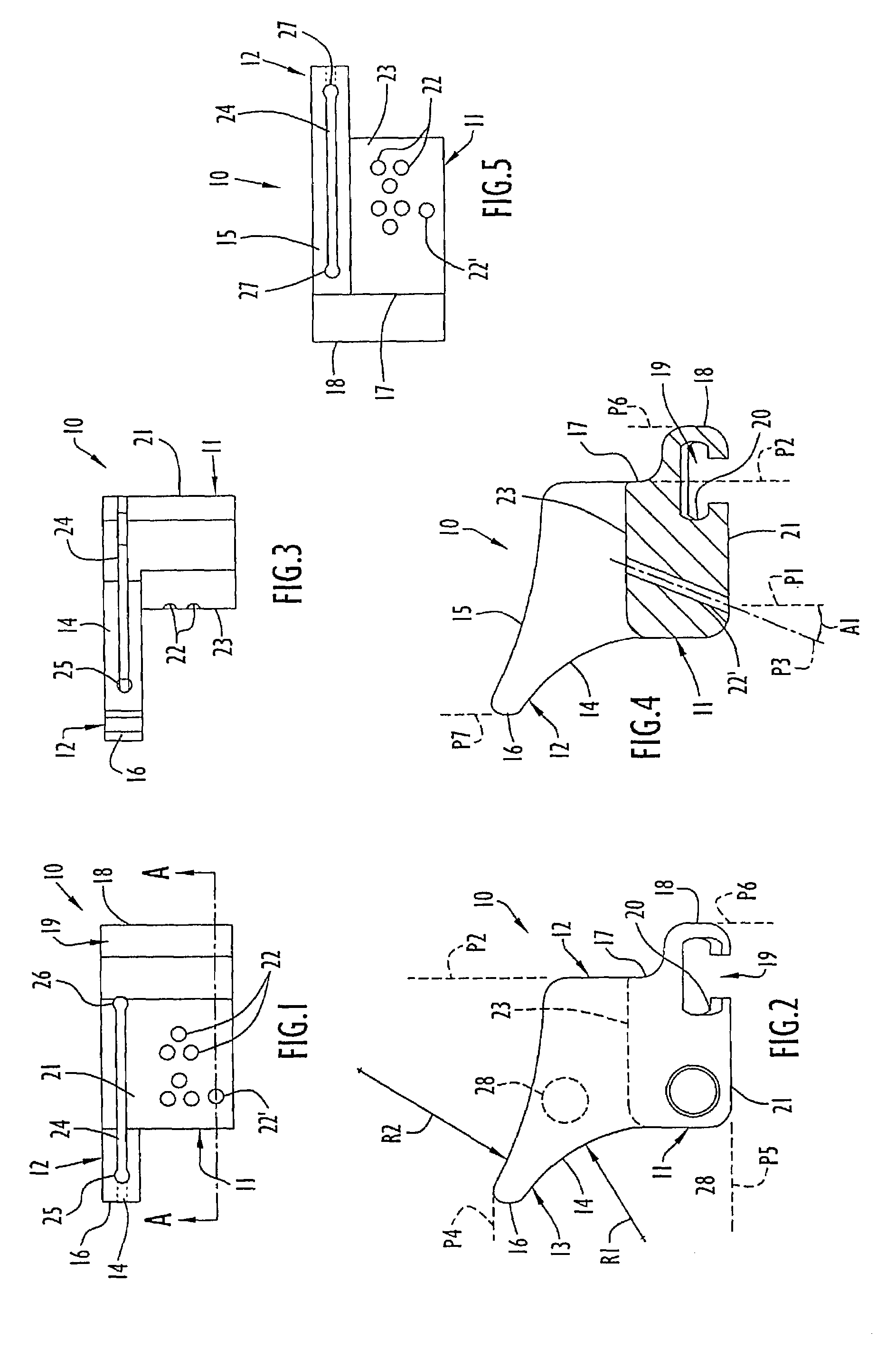
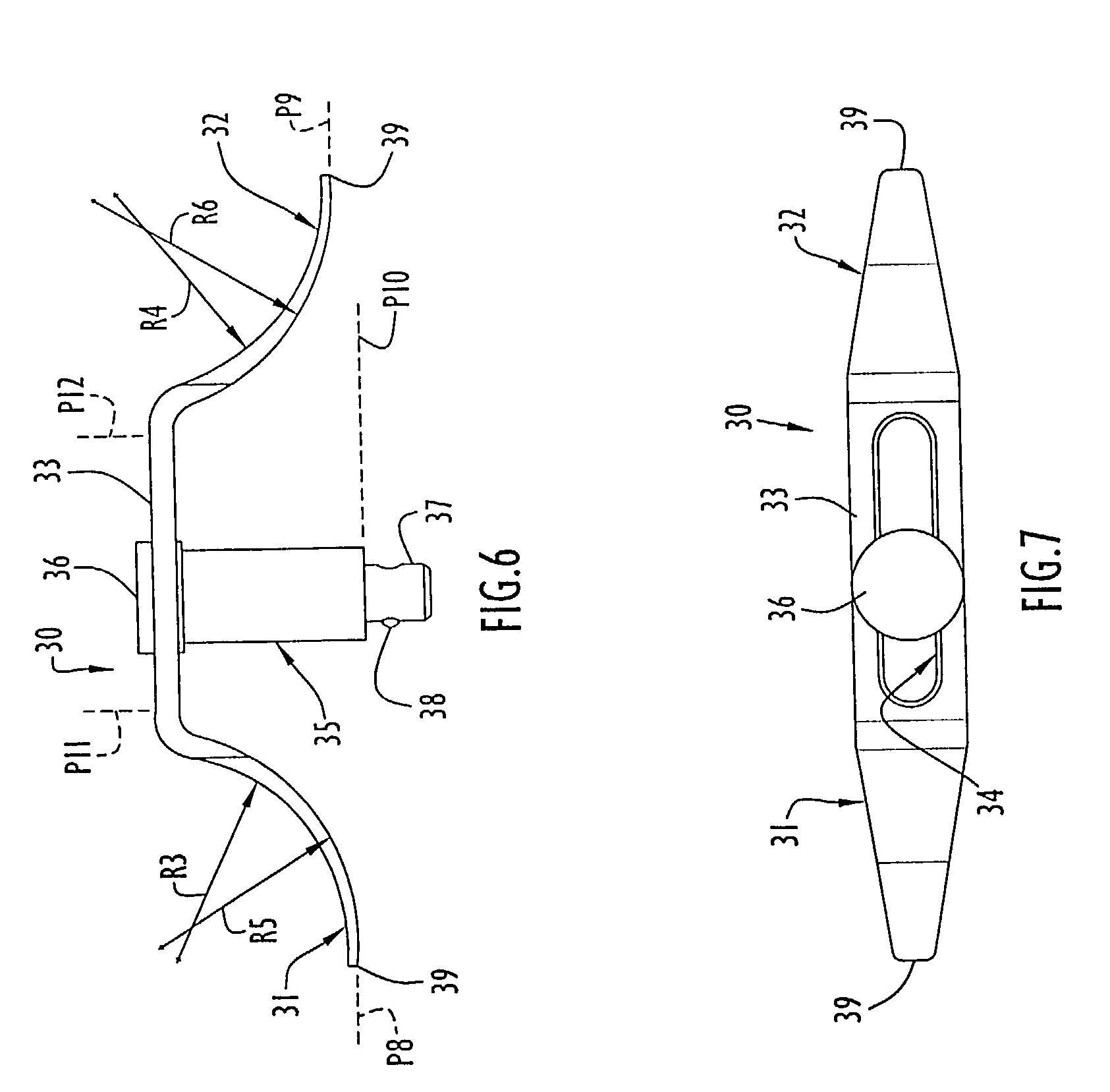
[0112]The instruments and methods of the present invention relate to implantation of knee joint prostheses and, in particular, to minimally invasive unicompartmental implantation of knee joint prostheses, especially the knee joint prostheses disclosed in the concurrently filed non-provisional patent applications entitled Knee Joint Prostheses, Prosthetic Femoral Components and Prosthetic Tibial Components, the entire disclosures of which were previously incorporated herein by reference. Accordingly, the knee joint prostheses and the prosthetic femoral and tibial components discussed herein include the knee joint prostheses and the prosthetic femoral and tibial components disclosed in the aforementioned patent applications. It should be appreciated, however, that the instruments and methods of the present invention may be used or adapted for use with other knee joint prostheses and may be performed using open surgical techniques. Although the instruments and methods of the present in...


PUM


Abstract

A method of minimally invasive unicompartmental knee replacement includes accessing a knee through a minimal incision, forming a planar surface along a tibial plateau of the knee, forming a planar posterior surface along a posterior aspect of the corresponding femoral condyle, resurfacing a distal aspect of the femoral condyle to form a resurfaced area having a curved portion, implanting a prosthetic tibial component on the planar surface along the tibial plateau and implanting a prosthetic femoral component on the prepared surface of the femoral condyle formed by the planar posterior surface and the resurfaced area. The curved portion of the resurfaced area has an anterior-posterior curvature corresponding to a fixation surface of the prosthetic femoral component. Prior to implantation, the femur and tibia are prepared to receive fixation structure of the femoral and tibial components.

Description

CROSS-REFERENCE TO RELATED PATENT APPLICATIONS[0001]This application claims priority from prior provisional patent application Ser. No. 60 / 333,488 filed Nov. 28, 2001, the entire disclosure of which is incorporated herein by reference. This application is related to the co-pending non-provisional patent applications filed concurrently herewith and entitled Knee Joint Prostheses (Ser. No. 10 / 305,370) and Instrumentation for Minimally Invasive Unicompartmental Knee Replacement (Ser. No. 10 / 305,371), the entire disclosures of which are incorporated herein by reference.BACKGROUND OF THE INVENTION[0002]1. Field of the Invention[0003]The present invention relates generally to knee replacement procedures and, more particularly, to methods of minimally invasive unicompartmental knee replacement.[0004]2. Brief Description of the Related Art[0005]Prosthetic knee joint components are increasingly used to repair knee joints damaged by trauma and / or disease. Basically, the natural knee joint inc...

Claims


Application Information

Patent Timeline
IPC IPC(8): A61F5/00A61B17/58A61B17/15A61B17/16
CPCA61B17/155A61B17/157A61B17/1675A61B17/1604A61B17/1659
Inventor ROSA, RICHARD A.HARTDEGEN, VERNON R.STOOKEY, ERIC A.HARRIS, JR., BRIAN R.FENCL, ROBERT M
Owner MICROPORT ORTHOPEDICS HLDG INC
Why Eureka
Try Eureka