
Hammer keyboard system and chassis

a keyboard system and keyboard technology, applied in the field of hammer and keyboard system, can solve the problems of increasing component count, limited layout arrangement, and hammer having to be formed in relatively complex shapes, so as to reduce the overall product cost of hammer, reduce the number of work processes for driving rivets, and reduce assembly costs

Inactive Publication Date: 2006-11-28
ROLAND CORP
View PDF2 Cites 18 Cited by
  • Summary
  • Abstract
  • Description
  • Claims
  • Application Information

AI Technical Summary

Benefits of technology

[0026]In accordance with the hammer of the present invention, three pass-through holes are drilled and disposed in the hammer main body and, together with this, two protrusions are formed on the mass plates. Therefore, when the mass plates are attached to the hammer main body, due to the fact that the two protrusions on the mass plates each fit into two of the pass-through holes from among the three pass-through holes of the hammer main body, it is possible to position the mass plates not only in the radial direction but also in the circumferential direction with respect to the hammer main body. In addition, by means of this positioning, it is possible for the linking holes of the mass plates to be linked through to the pass-through hole of the hammer main body. Accordingly, there is no need to carry out special work, as with the hammers of the past, to align each of the rivet holes with the others when the rivet is driven in and, since the attaching work is simplified, there is the advantageous result that the assembly costs can be reduced by that amount and it is possible to reduce the product cost of the hammer overall.
[0027]In addition, in accordance with the present invention, due to the fact that the two protrusions on the mass plates each fit into the pass-through holes, each of the mass plates is positioned and fixed not only in the radial direction but also in the circumferential direction with respect to the hammer main body. Therefore, even in those cases where the number of rivet members that are driven in is only one, it is possible to reliably fix each of the mass plates in the radial and circumferential directions without any rattling. As a result, since there is no need to drive in high-cost rivets in a plurality of locations as with the hammers of the past; and the number of components as well as the number of work processes for driving the rivets is reduced, there is the advantageous result that it is possible to lower the component costs and assembly costs by that amount and to further reduce the product costs of the hammer overall.
[0028]In addition, in accordance with the hammer of the present invention, each of the mass plates is fixed to the hammer main body by means of one rivet member. Therefore, since the number of drilling locations for the linking holes and pass-through holes in the mass plates and the hammer main body is kept to the lowest number possible and the diminution of the weight of the mass plates and the hammer man body can be limited, there is the advantageous result that it is possible to maintain the weight of the hammer overall by that amount. As a result, since the weight of each of the structural members that is required as a mass body that imparts the touch weight can be maintained with smaller outside dimensions, there is the advantageous result that it is possible to control the enlarging of the hammer overall.
[0029]In addition, in accordance with the keyboard system of the present invention, since it has the hammer of the present invention, there is the advantageous result that it is possible to lower the product costs for the keyboard system overall.
[0030]In accordance with the chassis of the present invention, the upper limit and lower limit control members, which control the swinging range of the hammer, are formed in a single unit with the chassis main body. Therefore, since there is no need to dispose a connecting bar and the like, which is required to form the control member in the case of the chassis of the past, on the front edge of the chassis and the space for the arrangement of the wiring and the edge plate and the like is maintained, there is the advantageous result that it is possible to appropriately dispose the wiring and the edge plate and the like on the front edge of the chassis and to limit the enlargement of the electronic musical instrument as well as damage to its appearance.
[0031]In addition, since there is no need to dispose and position the hammers shifted toward the rear edge of the chassis by the amount for the disposition of the connecting bar and the depth of the chassis can be shortened by that amount, there is the advantageous result that, in that area also, it is possible to limit the enlargement of the electronic musical instrument.

Problems solved by technology

With this kind of hammer, the arrangement of the layout must be limited to the space in the keyboard system, and the hammers are required to be formed in relatively complex shapes.
However, with the attachment structure discussed above, it is necessary to drive high-cost rivets into a multiple number of places and the component count increases.
In addition, since it is not possible to position each of the mass plates in the circumferential direction with respect to the hammer main body using only the alignment of the protrusions used for positioning and the concave portions, special work is required to position each of the rivet holes with the others.
As a result, component and assembly costs increase because of the increase in the component count as well as the added complexity of the attachment work, and the product cost of the hammer overall rises.
Thus, when the number of locations in which the rivet holes are drilled in the mass plates is in proportion to the number of rivets employed, the weight of the hammer overall is lightened by that amount and it is not possible for the function of the mass plates that impart the touch weight to be fully manifested.
This leads to the enlarging of the hammer overall.
In addition, with the chassis structure discussed above, since the connecting bar and the guide member are disposed on the front edge of the chassis, there is the problem that the space for arranging the wiring (the electrical cabling) and the edge plate (the wooden plate that is disposed below the front edge of the white keys) and the like is reduced by that amount.
Thus, the electronic musical instrument becomes larger and its appearance is blemished.
Because of this, the swinging range of the hammer at the time of the key pressing is limited.
By this means, the swinging range of the hammer at the time of the key releasing is limited.

Method used


Image

  • Hammer keyboard system and chassis
  • Hammer keyboard system and chassis
  • Hammer keyboard system and chassis

Examples


Embodiment Construction

[0041]In the following description of preferred embodiments, reference is made to the accompanying drawings which form a part hereof, and in which are shown by way of illustration specific embodiments in which the invention may be practiced. It is to be understood that other embodiments may be utilized and structural changes may be made without departing from the scope of the preferred embodiments of the present invention.

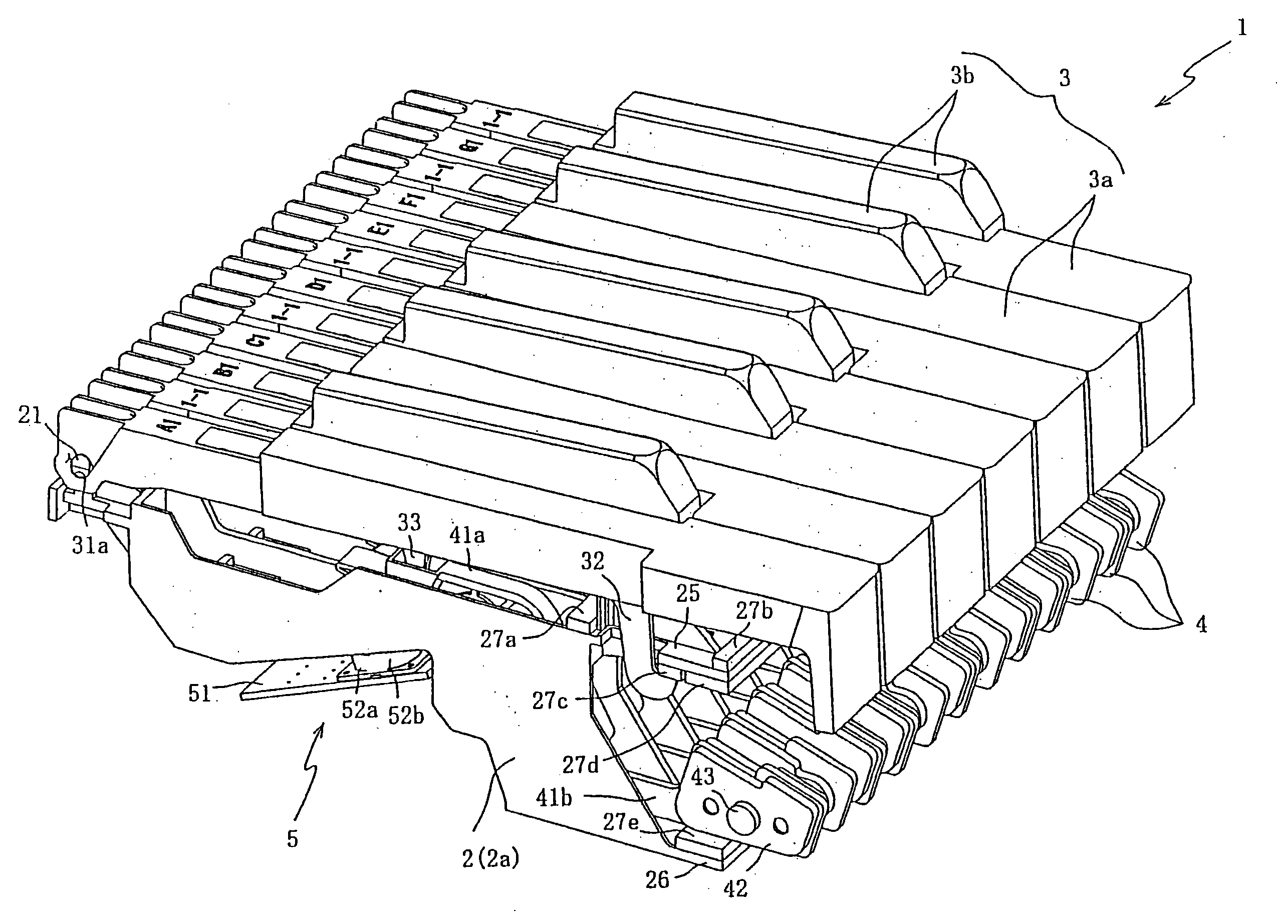
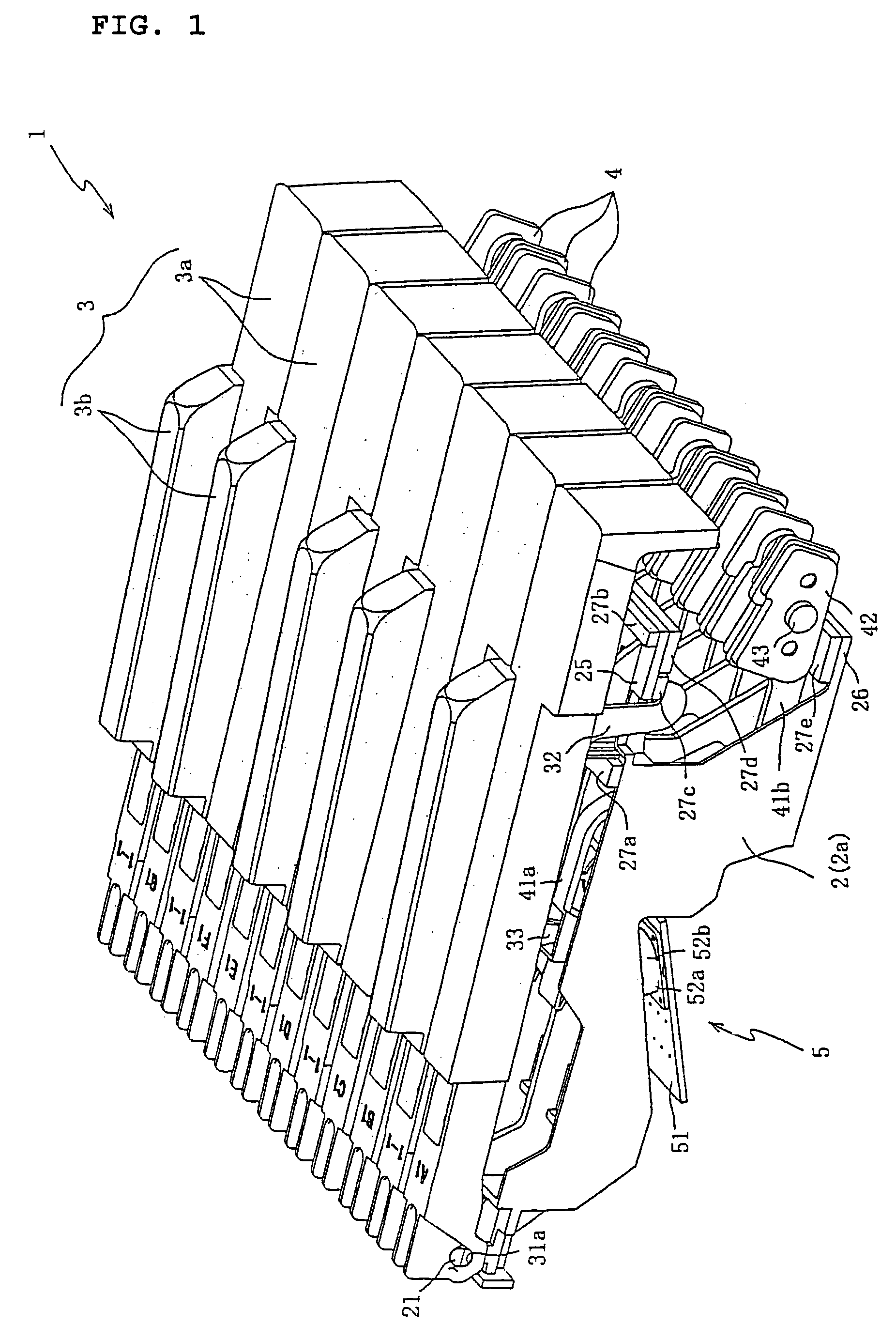
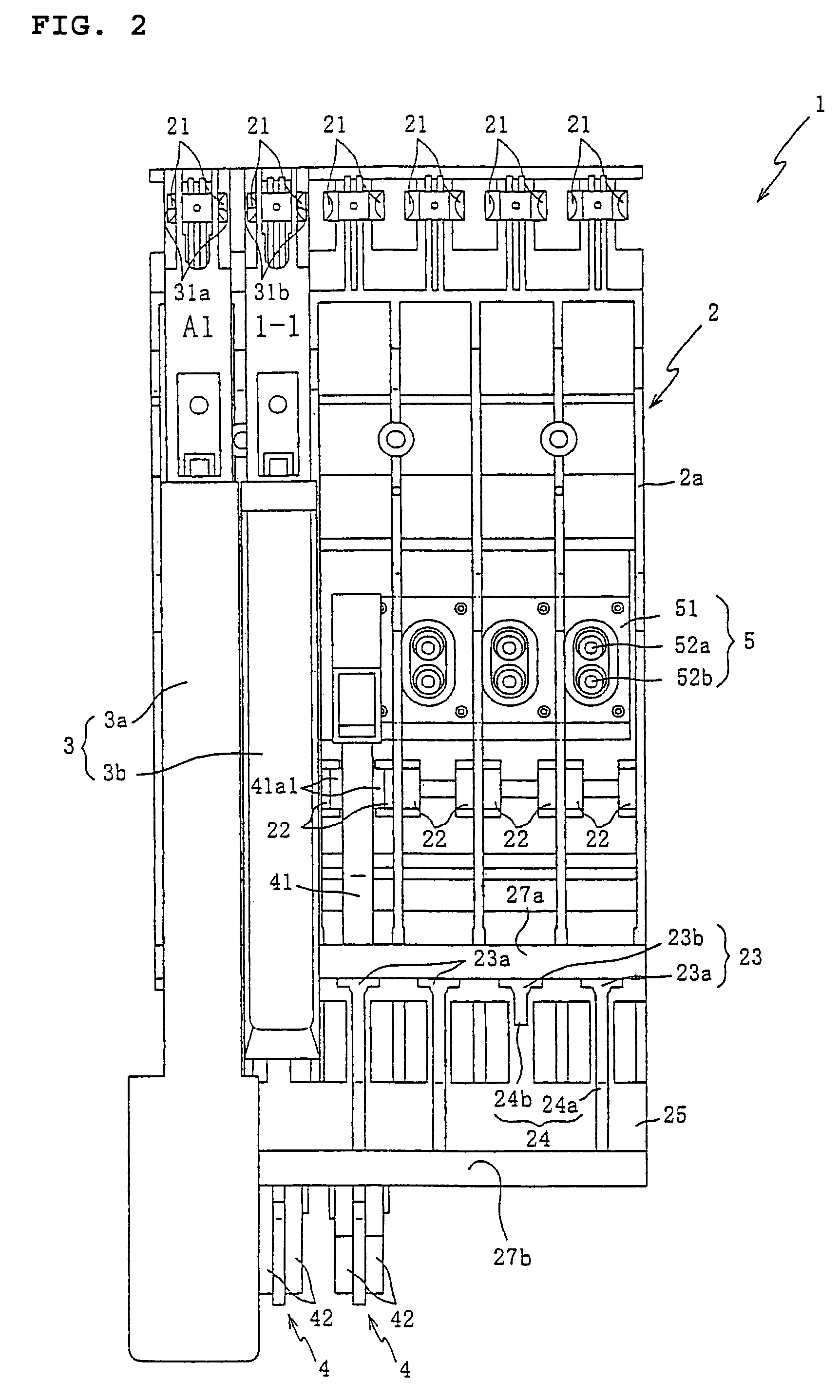
[0042]FIG. 1 is an oblique drawing of the keyboard system 1 in which the hammer 4 in one preferred embodiment of the present invention is used. Incidentally, in FIG. 1, the keyboard system 1 is abbreviated in its width in the right to left direction (the direction in which the row of keys 3 is disposed) and only a section of 12 keys is shown in the drawing. First, an explanation will be given of the exterior structure of the keyboard system 1, referring to FIG. 1.

[0043]The keyboard system 1 is configured for operation of the keyboard by the performer and is a syste...


PUM


Abstract

A hammer with simplified structure and reduced costs that maintains its capability as a mass body to impart a touch weight. The hammer is configured such that it is possible to fix the two mass plates to the metal base plate by means of a single rivet. Therefore, the number of places in which the rivet holes are drilled and disposed in both mass plates and the metal base plate are kept to a minimum, and it is possible to limit the lightening of the weight of both mass plates and the metal base plate by that amount. As a result, since it is possible to configure the base plates and the metal base plate with smaller dimensions while maintaining the required weight, the capability as a mass body to impart a touch weight can be maintained while preventing the enlarging of the hammer overall.

Description

CROSS-REFERENCE TO RELATED APPLICATIONS[0001]The present application claims priority from Japanese Patent Application No. 2003-138978, filed May 16, 2003, and Japanese Patent Application No. 2003-139057, filed May 16, 2003, both of which are hereby incorporated by reference herein.BACKGROUND[0002]1. Field of the Invention[0003]The present invention relates to a hammer and a keyboard system and, in particular, to a hammer having a simplified structure and reduced costs and that maintains its capability as a mass body to impart a touch weight. The present invention also relates to a keyboard system comprising the hammer. In addition, the present invention relates to a chassis and, in particular, to a chassis in which the chassis main body and the control member are formed as a single unit and with which it is possible to miniaturize the design of the electronic musical instrument overall.[0004]2. Description of Related Art[0005]For some time, hammers have been installed in keyboard sy...

Claims


Application Information

Patent Timeline
Patent Type & Authority Patents(United States)
IPC IPC(8): G10C3/18G10H1/34
CPCG10H1/346
Inventor UNO, SHIROSATO, HITOSHI
Owner ROLAND CORP
Learn More