Active-passive electromagnetic shielding to reduce MRI acoustic noise

a passive electromagnetic shielding and mri scanner technology, applied in the field of low acoustic noise mri scanner, can solve the problems of many medical patients' objectionable, cryostat and other metallic parts of the magnet assembly are also sources of vibration and acoustic noise, and achieve the effect of reducing acoustic nois

Inactive Publication Date: 2006-11-28
SHARKSTONE
View PDF11 Cites 33 Cited by
  • Summary
  • Abstract
  • Description
  • Claims
  • Application Information

AI Technical Summary

Benefits of technology

[0016]The present invention provides a method and apparatus for generating magnetic resonance images with reduced acoustic noise. In one embodiment, such an apparatus includes a gradient coil assembly passive shielding element including at least one conducting element outside the actively shielded gradient coil winding. The passive shielding element is located outside the gradient winding elements and is positioned to substantially block leakage fields that can otherwise produce eddy currents in the magnet cryostat and other magnet structures.

Problems solved by technology

Generally, the various components of the MRI scanner represent sources and pathways of acoustic noise that can be objectionable to the patient being imaged and to the operator of the scanner.
For example, the gradient coil assembly generates loud acoustic noises, which many medical patients find objectionable.
The magnet cryostat and other metallic parts of the magnet assembly are also sources of vibration and acoustic noise.
However, the active gradient shielding is not perfect, as some pulsed magnetic fields leak through and around the shielding windings, interact with the magnet or cryostat structure and cause eddy currents in those structures.
Some recent designs to improve gradient active shielding produce increasingly complex gradient current patterns.
Compromises thereby incurred limit the effectiveness of the additional shielding achieved.
The recent quest for shorter length and rapidly changing gradients has also tended to work against effective shielding.
This arrangement is not the best configuration to produce the most effective shielding.
Passive shielding alone will not provide adequate shielding and eddy current control because of its finite time constants.
Multiple layers of active gradient shielding will have limited effectiveness because active gradient shielding must have discrete current paths.

Method used


Image

  • Active-passive electromagnetic shielding to reduce MRI acoustic noise
  • Active-passive electromagnetic shielding to reduce MRI acoustic noise
  • Active-passive electromagnetic shielding to reduce MRI acoustic noise

Examples


Embodiment Construction

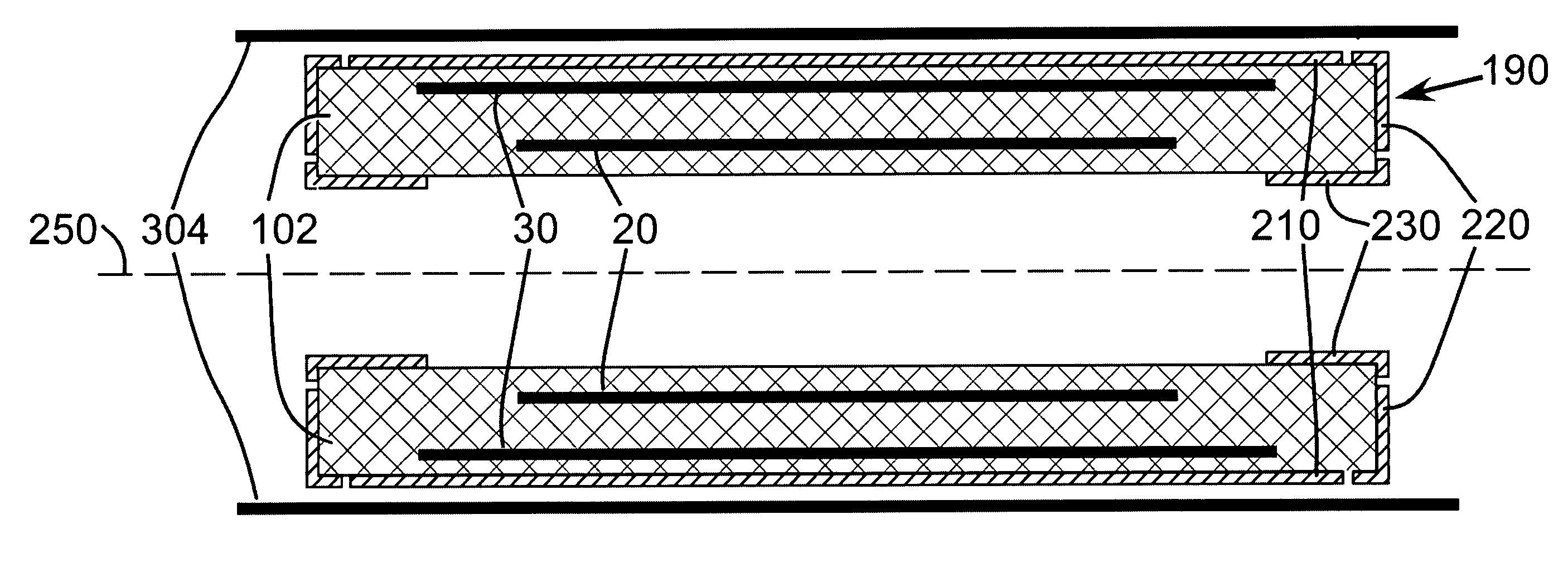
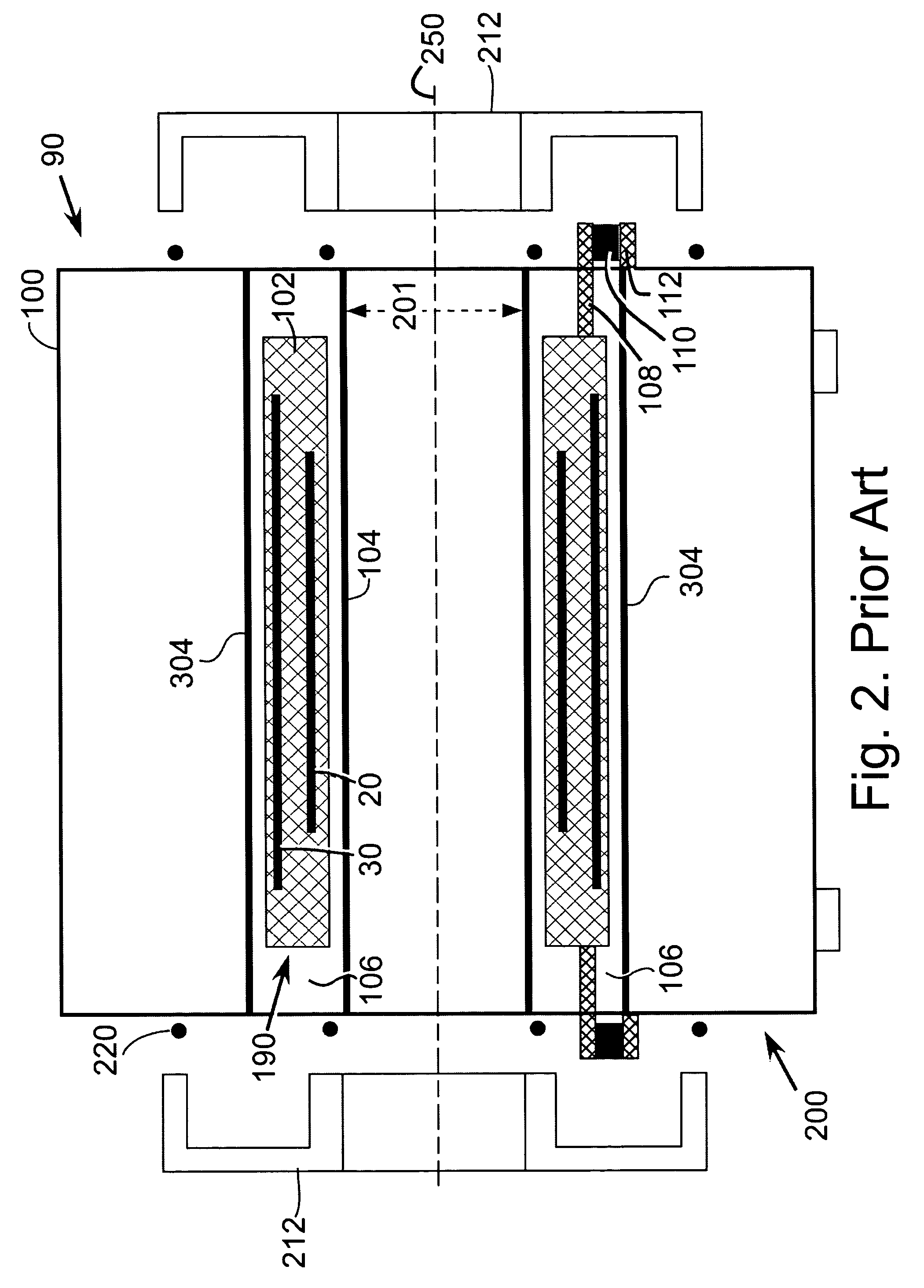
[0029]Referring to FIG. 2 there is shown an illustrative MRI device 90 to which embodiments of the present invention are applicable. MRI device 90 is of a type useful in producing magnetic resonance (MR) images of a patient or subject. Throughout the figures, like numerals represent like elements. FIGS. 1–6 show MRI device 90 based on a closed, cylindrical superconducting magnet assembly 200. It is to be appreciated by one skilled in the art that the functions and descriptions of the present invention are equally applicable to an open magnet configuration.

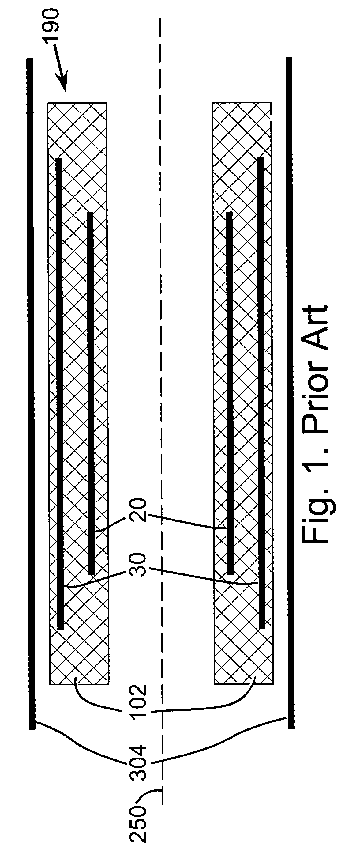
[0030]FIG. 1 is a cross-sectional side view of a prior art actively shielded gradient assembly. The actively shielded gradient coil winding consists of an inner active gradient winding portion 20 and an outer gradient winding portion 30. Generally these are electrically connected in series and powered by a single power amplifier. They could be powered by two separate power amplifiers. The active gradient coil winding 20 plus 30 is ...


PUM


Abstract

The present invention provides an apparatus for reducing acoustic noise in a magnetic resonance imaging device including passive shielding located outside the actively shielded gradient winding elements in order to reduce the magnitude of fields that spread outside the gradient coil assembly in unwanted directions and interact with the magnet cryostat or other metallic magnet parts, inducing eddy currents that cause consequent acoustic noise. The passive shielding elements are conducting layers located on the outer radius of the cylindrical gradient coil assembly in a cylindrical magnet system, conducting layers located at the ends of the gradient coil assembly in a cylindrical magnet system, and conducting layers located inside the actively shielded gradient winding inner elements in a cylindrical magnet system. The passive shielding could also be located on separate structures that are vibrationally isolated from the magnet cryostat. The actively shielded gradient winding can also be extended to portions at the ends of the actively shielded gradient winding and further to portions inside the inner radius of the inner portion of the actively shielded gradient winding. The actively shielded gradient windings and passive shielding should be designed concurrently in order to substantially optimize the gradient linearity and reduce the eddy currents generated in metallic parts of the magnetic resonance imaging system.

Description

[0001]This application claims the benefit of: U.S. Provisional Application No. 60 / 497,267, filed Aug. 25, 2003; U.S. Provisional Application No. 60 / 500,225, filed Sep. 5, 2003; and U.S. Provisional Application No. 60 / 570,593, filed May 13, 2004, which are hereby incorporated herein by reference.BACKGROUND OF THE INVENTION[0002]The present invention relates generally to a magnetic resonance imaging (MRI) scanner and more particularly to a low acoustic noise MRI scanner.[0003]MRI scanners, which are used in various fields such as medical diagnostics, typically create images based on the operation of a magnet, a gradient coil assembly, and a radiofrequency coil(s). The magnet creates a uniform main magnetic field that makes unpaired nuclear spins, such as hydrogen atomic nuclei, responsive to radiofrequency excitation via the process of nuclear magnetic resonance (NMR). The gradient coil assembly imposes a series of pulsed, spatial-gradient magnetic fields upon the main magnetic field ...

Claims


Application Information

Patent Timeline
Patent Type & Authority Patents(United States)
IPC IPC(8): G01V3/00G01R33/385G01R33/421
CPCG01R33/3854G01R33/4215
Inventor EDELSTEIN, WILLIAM AKIDANE, TESFAYE K.TARACILLA, VICTORBAIG, TANVIR N.EAGAN, TIMOTHY P.BROWN, ROBERT W.
Owner SHARKSTONE
Why Eureka
Try Eureka