Device for detecting degradation of a component

a technology for detecting components and components, applied in the direction of resistance/reactance/impedence, instruments, mechanical means, etc., can solve the problems of no permanent electrical connection or permanent electromagnetic coupling, and achieve the effect of simple, fast and reliable recording

Inactive Publication Date: 2006-11-28
SIEMENS AG
View PDF17 Cites 26 Cited by
  • Summary
  • Abstract
  • Description
  • Claims
  • Application Information

AI Technical Summary

Benefits of technology

[0007]It is an object of the invention to show how degradation of a component can be recorded simply, quickly and reliably.

Problems solved by technology

Moreover, there is no permanent electrical connection or permanent electromagnetic coupling.

Method used


Image

  • Device for detecting degradation of a component
  • Device for detecting degradation of a component
  • Device for detecting degradation of a component

Examples


example 1

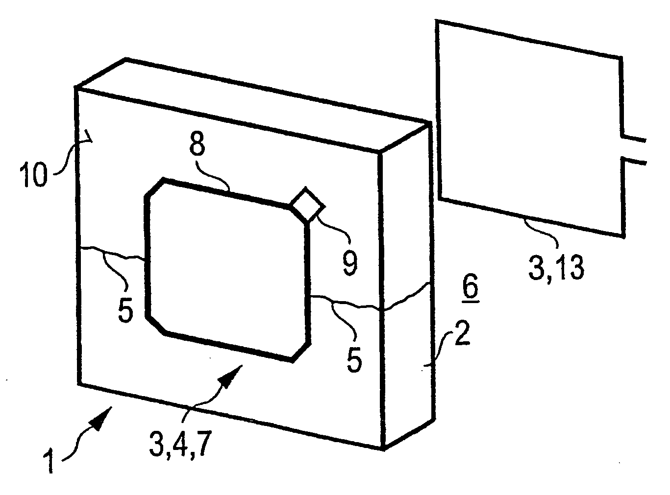
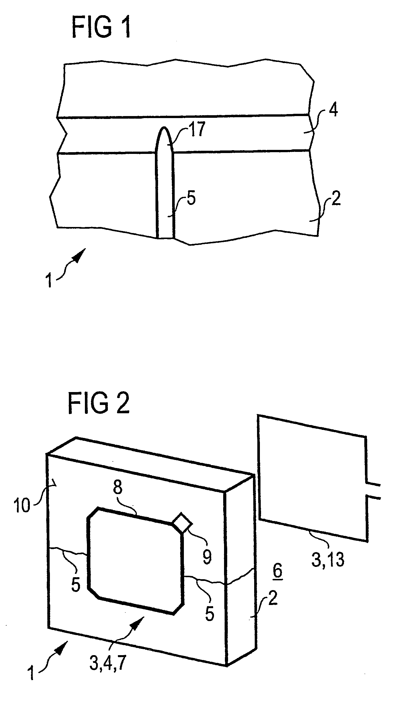
[0045]The arrangement 1 comprises a component 2 in the form of a heat shield and a monitoring device 3 for recording degradation 5 of the component 1 (FIG. 2). The monitoring device 3 has an electrically conductive monitoring structure 4 with a defined electrical property applied to a surface portion 10 of the heat shield 1. The monitoring device 3 and the monitoring structure 4 are not permanently electrically connected to one another.

[0046]The surface portion 10 is, for example, remote from the interior space 6 of a combustion chamber. The monitoring structure is a resonant circuit 7 comprising an interconnect 8 and a capacitor 9. The degradation 5 that is to be recorded is a propagation of an existing crack.

[0047]The heat shield 2 includes a ceramic as component material. The ceramic is mullite. The conductor material of the monitoring structure 4 is an electrically conductive ceramic conductor which is able to withstand temperatures of up to 800° C. The conductor material and th...

example 2

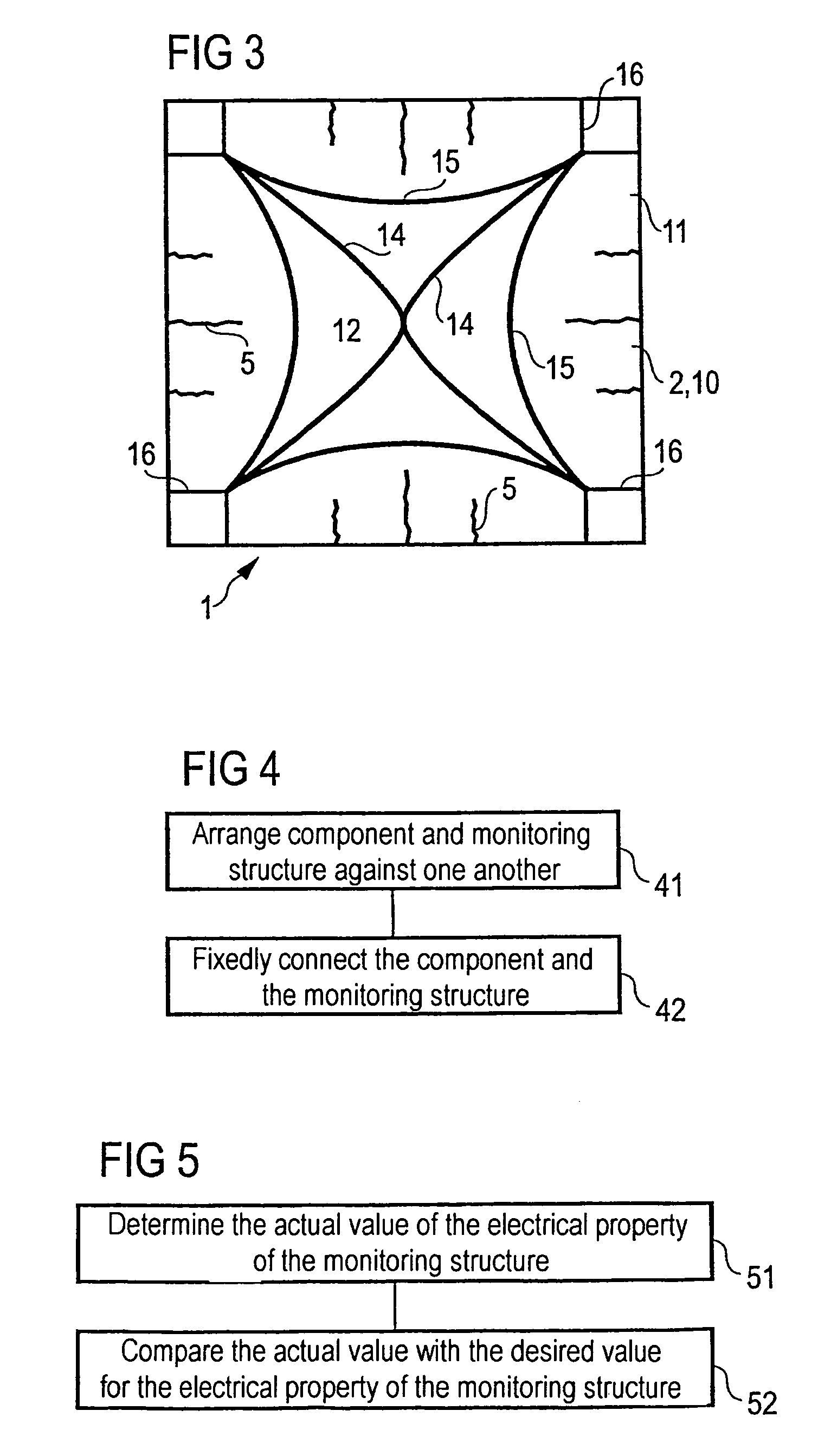
[0053]Unlike in the arrangement described above, the monitoring structure 4 comprises a network of internal interconnects 14 and external interconnects 14. Each of the interconnects 14 and 15 is distinguished by a defined DC resistance. At those locations of the heat shield 2 which are not influenced by cracks 5, the interconnects 14 and 15, as electrical contact locations 16 for determining the electrical property of the monitoring structure, are routed as far as the edge of the heat shield 2. The internal interconnects 14 are not normally influenced by cracks 5. They are used to check the contact locations 16 during the determination of the DC resistance of the monitoring structure. For this purpose, the internal interconnects 14 have a different electrical resistance than the external interconnects 15.

[0054]The monitoring device 3 and the monitoring structure 4 are not permanently electrically connected to one another. An electrical connection (coupling) between monitoring device...

example 3

[0056]The arrangement described above is used to record degradation of the heat shield not by measuring the DC resistance of the monitoring structure 4, but rather by measuring the frequency-dependent impedance of the monitoring structure.


PUM

PropertyMeasurementUnit
temperatureaaaaaaaaaa
surface temperatureaaaaaaaaaa
temperaturesaaaaaaaaaa

Abstract

An apparatus for monitoring the structural integrity of a component. A monitoring structure is applied to a component that is subject to structural degradation. The monitoring structure includes an electrical conductor that becomes cracked if the component becomes structurally degraded. When the component is a ductile metal component that may be degraded by bending, the electrical conductor is formed of a brittle material that cracks when the ductile metal component is bent. When the component is a brittle ceramic heat shield wherein a crack having a critical length is of concern, the electrical conductor is located at a predetermined location wherein a critical length crack in the component will propagate into the conductor. A crack in the electrical conductor is detected with a monitoring device to indicate a degraded structural condition in the component.

Description

CROSS REFERENCE TO RELATED APPLICATION[0001]This application is the US National Stage of International Application No. PCT / DE03 / 01658, filed May 22, 2003 and claims the benefit thereof. The International Application claims the benefits of German application No. 10223958.1 DE filed May 29, 2002, both of the applications are incorporated by reference herein in their entirety.FIELD OF THE INVENTION[0002]The invention relates to an arrangement comprising a component and at least one monitoring device for recording degradation of the component. The invention also provides a process for producing the arrangement and a method for checking the ability of the component to function using the arrangement.BACKGROUND OF THE INVENTION[0003]DE 36 36 321 A1 shows an arrangement and a method for determining the state of wear of a component.[0004]An arrangement of the abovementioned type is known, for example, in the context of a combustion chamber of a gas turbine. The combustion chamber has an inte...

Claims


Application Information

Patent Timeline
Patent Type & Authority Patents(United States)
IPC IPC(8): G01R27/08G01N19/08G01N3/02G01N3/06G01N27/20G01N33/38
CPCG01N3/066G01N33/388G01N2203/0066G01N2203/0226G01N2203/0244G01N2203/0664
Inventor BAST, ULRICHLAMPENSCHERF, STEFANRETTIG, UWE
Owner SIEMENS AG
Why Eureka
Try Eureka