Method for mismatch detection between the frequency of illumination source and the duration of optical integration time for imager with rolling shutter

a technology of imager and rolling shutter, applied in the field of cmos imager and imaging system, can solve problems such as flickering or “running bands” in the image fram

Active Publication Date: 2006-11-28
APTINA IMAGING CORP
View PDF2 Cites 42 Cited by
  • Summary
  • Abstract
  • Description
  • Claims
  • Application Information

AI Technical Summary

Benefits of technology

[0006]These and other features of the invention will be more clearly understood from the following detailed description, which is provided in connection with the accompanying drawings.

Problems solved by technology

Under certain conditions described below, this method of integration time control leads to the possibility of flicker or “running bands” in the image frame.

Method used


Image

  • Method for mismatch detection between the frequency of illumination source and the duration of optical integration time for imager with rolling shutter
  • Method for mismatch detection between the frequency of illumination source and the duration of optical integration time for imager with rolling shutter
  • Method for mismatch detection between the frequency of illumination source and the duration of optical integration time for imager with rolling shutter

Examples


Embodiment Construction

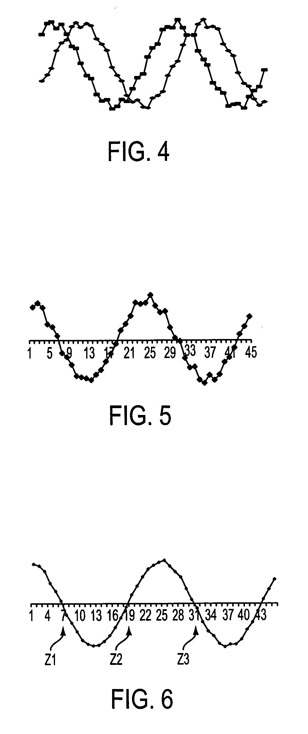
[0021]Most fluorescent illuminators produce alternate light intensity. Irradiated light intensity, L(t), has the frequency that is twice that of AC power supply in use, f(t).

L(t)=A sin(2πft)2  (1)

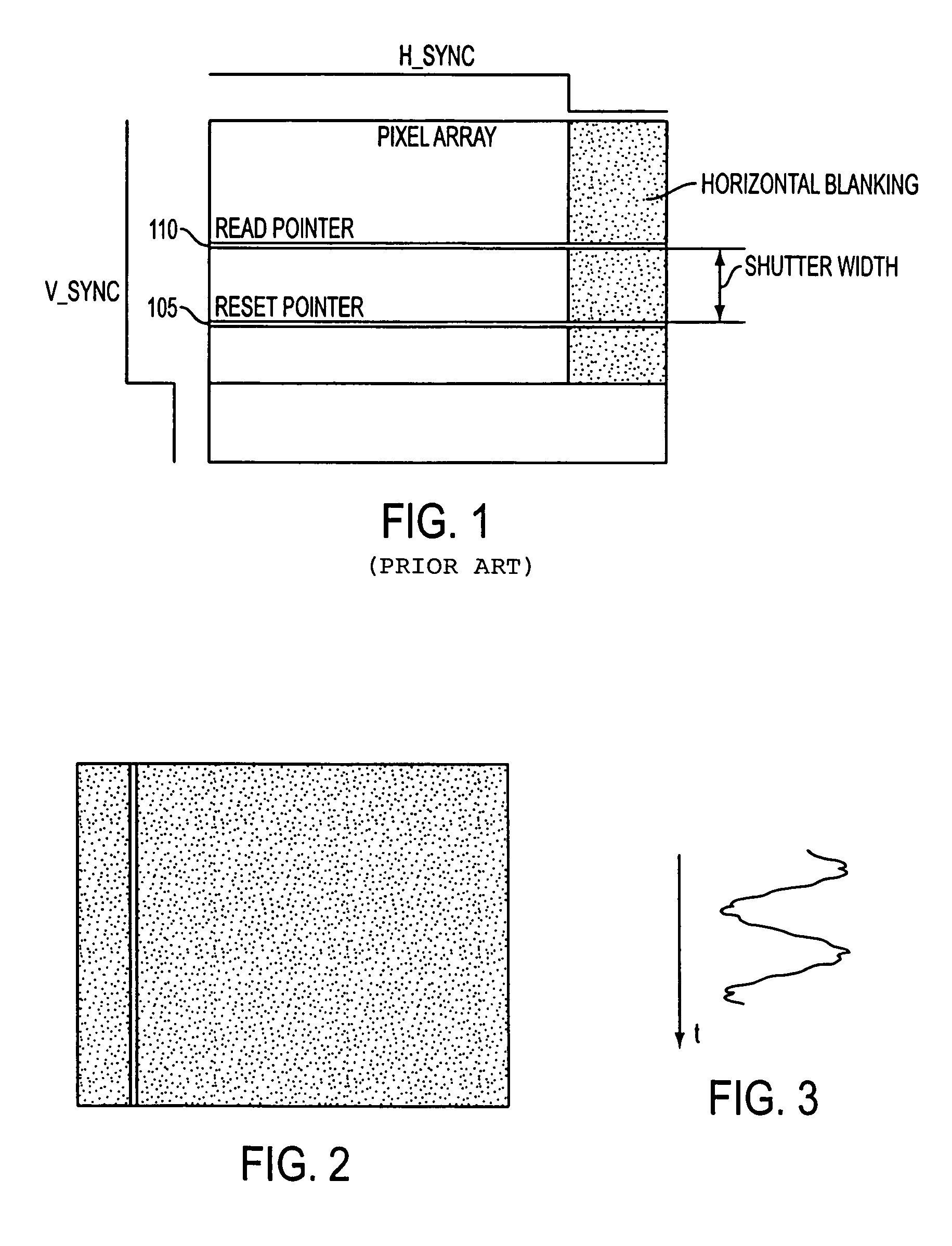
[0022]Signal level accumulated in the pixels of CMOS image sensor with rolling shutter operation is proportional to the integration time IT (exposure or shutter width). Flicker occurs when the shutter width is not an integer multiple of the period of the light intensity. In imagers with rolling shutter operation, flicker manifests itself as dark and bright bands “running” through the image. In this situation, the signal accumulated by the pixels in a given row depends on the phase relationship between optical integration time and the period of the light intensity fluctuation. This can be expressed as an integral of light intensity over integration time as:

[0023]g⁡(T0)=⁢∫T0T0+IT⁢L⁡(t)⁢⁢ⅆt=⁢A4⁢π·f⁢(2⁢π·f·IT+cos⁡(2⁢π·f⁡(2⁢T0+IT))·⁢sin⁡(2⁢π·fIT)(2)

where T0 is the time corresponding to the begin...


PUM


Abstract

A method for achieving flickerless operation of imagers using a rolling shutter, including the steps of detecting flicker in an image frame and adjusting an integration time such that the integration time is an integer multiple of a light intensity period, is described. The method reduces the task of detecting flicker to detecting a spatial sine wave in the image frame by subtracting two image frames from each other. The subtraction reduces or eliminates image content from the image frames and makes the detection process independent of image content. This method can be practiced based on a very short sequence of image frames (as few as two image frames) and is virtually insusceptible to motion of the image content. Adjustments to the integration time are made by changing the horizontal blanking time of the imager and, thereby extending the duration time of each row of said image frame.

Description

FIELD OF THE INVENTION[0001]The present invention relates to the field of CMOS imagers and imaging systems using CMOS imagers and, in particular to CMOS imagers using a rolling shutter.BACKGROUND OF THE INVENTION[0002]In many modern CMOS imagers employing pixel arrays the optical integration time is controlled by the method known as “rolling shutter”. This approach utilizes at least two pointers, Reset and Read, that continuously move through the pixel array image frame from top to bottom jumping from line to line at line-time intervals. First, the Reset pointer 105 starts the integration for all pixels in the line. Some time later the Read pointer 110 reaches the same line and initiates signal readout. This is illustrated in FIG. 1, which depicts a pixel array. The distance in lines between the two pointers is referred to as shutter width 115. Shutter width multiplied by the line time gives the duration of the optical integration time.[0003]The use of “rolling shutter” approach all...

Claims


Application Information

Patent Timeline
Patent Type & Authority Patents(United States)
IPC IPC(8): H04N9/73H04N5/235
CPCH04N5/235H04N5/2353H04N5/2357H04N23/70H04N23/745H04N23/73
Inventor KAPLINSKY, MICHAELSUBBOTIN, IGOR
Owner APTINA IMAGING CORP
Why Eureka
Try Eureka