
Database system

Inactive Publication Date: 2006-11-28
HITACHI LTD
View PDF19 Cites 37 Cited by
  • Summary
  • Abstract
  • Description
  • Claims
  • Application Information

AI Technical Summary

Benefits of technology

[0009]It is an object of the present invention to provide a technique by which the burden that would be otherwise imposed on a user due to execution of commands can be relieved, and the processing of a change can be performed rapidly.
[0011]According to the aforementioned technique, a specified partition change is executed automatically as soon as the occurrence of the partition change trigger is detected. Thus, the burden imposed on the user can be relieved.
[0012]According to the aforementioned technique, in the step of migrating data necessary to migrate from one data storage area to another data storage area includes the step of executing migrations of pieces of data in parallel as long as a migration source storage area and a migration destination storage area of one piece of the data do not overlap those of another piece of the data when a plurality of data migrations are required. Accordingly, as for migrations of data among the storage areas, pieces of data can be migrated in parallel as long as the migration source area and the migration destination area of one piece of the data do not overlap those of another piece of the data. Thus, the processing of the data migrations can be executed efficiently.

Problems solved by technology

In this event, maintenance of partitions and storage areas due to the revision of the ranges of the data requires a management cost because the unnecessary data has to be deleted manually.
However, the access frequency will decrease as time progresses, and finally access will be rarely gained to the data.
Thus, according to simple key range partitioning, frequent access to a partition storing new data results in concentration of loads on the partition.
Thus, a large number of commands are required.
In a technique disclosed in JP-A-2000-67077, only the operation to delete partitions and the operation to add partitions are executed automatically, but it is not possible to support the automation of the operation to integrate ranges so that data fragmented in partitions each having a small range are rearranged in a partition having a large range.
Thus, a large burden is imposed on a user.

Method used


Image

  • Database system
  • Database system
  • Database system

Examples


Embodiment Construction

[0028]A database system according to the present invention includes a technique in which a data migration point and a migration method are defined in advance, whereupon the occurrence of the data migration point is monitored, and data is migrated, for example, automatically on the basis of the defined data migration method when the data migration point is detected.

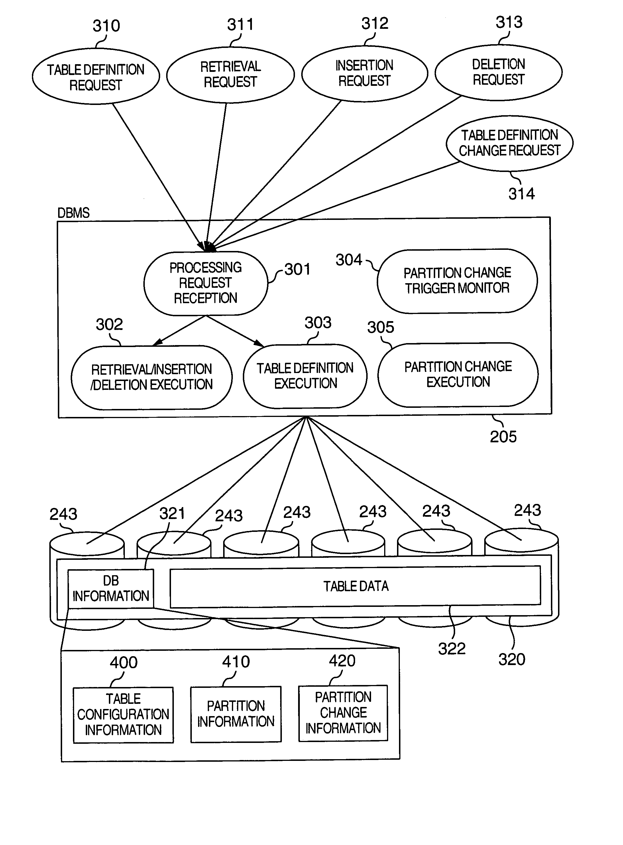
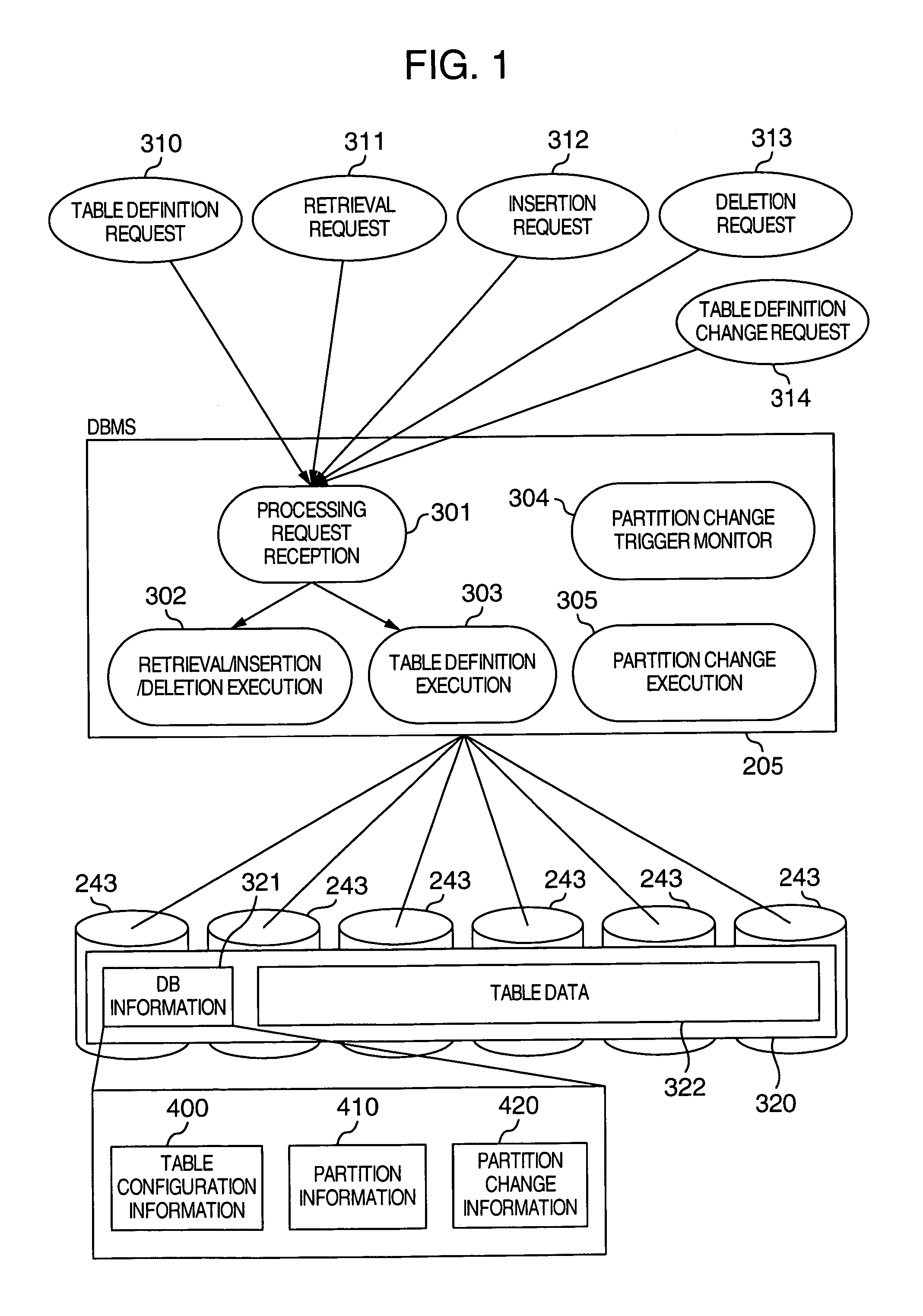
[0029]With reference to the drawings, description will be made below on a database system according to an embodiment of the present invention. FIG. 1 is a diagram showing an example of the configuration of a DBMS (DataBase Management System) according to an embodiment of the present invention. As shown in FIG. 1, upon acceptance of a processing request such as a table definition request 310, a retrieval request 311, an insertion request 312, a deletion request 313, a table definition change request 314 or the like in a processing request reception 301, a DBMS 205 analyzes the accepted request and executes requested process...


PUM


Abstract

When a trigger and a method for changing partition definition information have been defined, a DBMS monitors the occurrence of the trigger. When the occurrence of the trigger is detected, a specified partition change is executed automatically. When the partition change is executed, migrations of data among storage areas are executed in parallel as long as the migration source storage area and the migration destination storage area of one piece of the data do not overlap those of another piece of the data.

Description

BACKGROUND OF THE INVENTION[0001]The present invention relates to a database system, and particularly relates to a database system processing technique for partitioning a database table based on key range partitioning in a relational database system.[0002]One of database systems is a relational database system, in which a database is constituted by a table that can be observed in a two-dimensional table format by a user, and the table is constituted by a plurality of rows. In addition, each row is constituted by a plurality of columns, and each column has a data type and a data length defining the properties of the column. In the relational database system, the table constituting the database is partitioned and stored to improve the throughput in the system. That is, in the database system, table data are fragmented and stored in a plurality of storage areas (horizontal (row) partitioning of the table) so that the load of accesses to the table can be dispersed. Key range partitionin...

Claims


Application Information

Patent Timeline
IPC IPC(8): G06F17/30G06F12/00G06F7/00
CPCG06F17/30339Y10S707/99943G06F16/2282
Inventor NAKANO, YUKIOSUGIMOTO, YUKI
Owner HITACHI LTD
Learn More