Method and apparatus for concurrent engineering and design synchronization of multiple tools

a technology of engineering and design, applied in the direction of instruments, digital computers, computing, etc., can solve the problems of manual change of connectivity, loss of data, and cumbersome design process, and achieve the effect of easy control and synchronization of the design process

Active Publication Date: 2006-11-28
CADENCE DESIGN SYST INC
View PDF5 Cites 96 Cited by
  • Summary
  • Abstract
  • Description
  • Claims
  • Application Information

AI Technical Summary

Benefits of technology

[0011]The present inventor has realized the need for an integrated system that enables concurrent engineering between design entry and layout. The present invention includes a schema for connectivity that can be shared between the design entry and layout tools. It can also be used for generating HDL and analog net list. Included is a methodology on how each tool used by designers should update connectivity changes so as to m

Problems solved by technology

One of the problems in this architecture is that changes like connectivity changes have to be either done manually or using design differences and design association tools.
There could be loss of data if the user forgets a step in the flow.
And, although advanced to

Method used


Image

  • Method and apparatus for concurrent engineering and design synchronization of multiple tools
  • Method and apparatus for concurrent engineering and design synchronization of multiple tools
  • Method and apparatus for concurrent engineering and design synchronization of multiple tools

Examples


Embodiment Construction

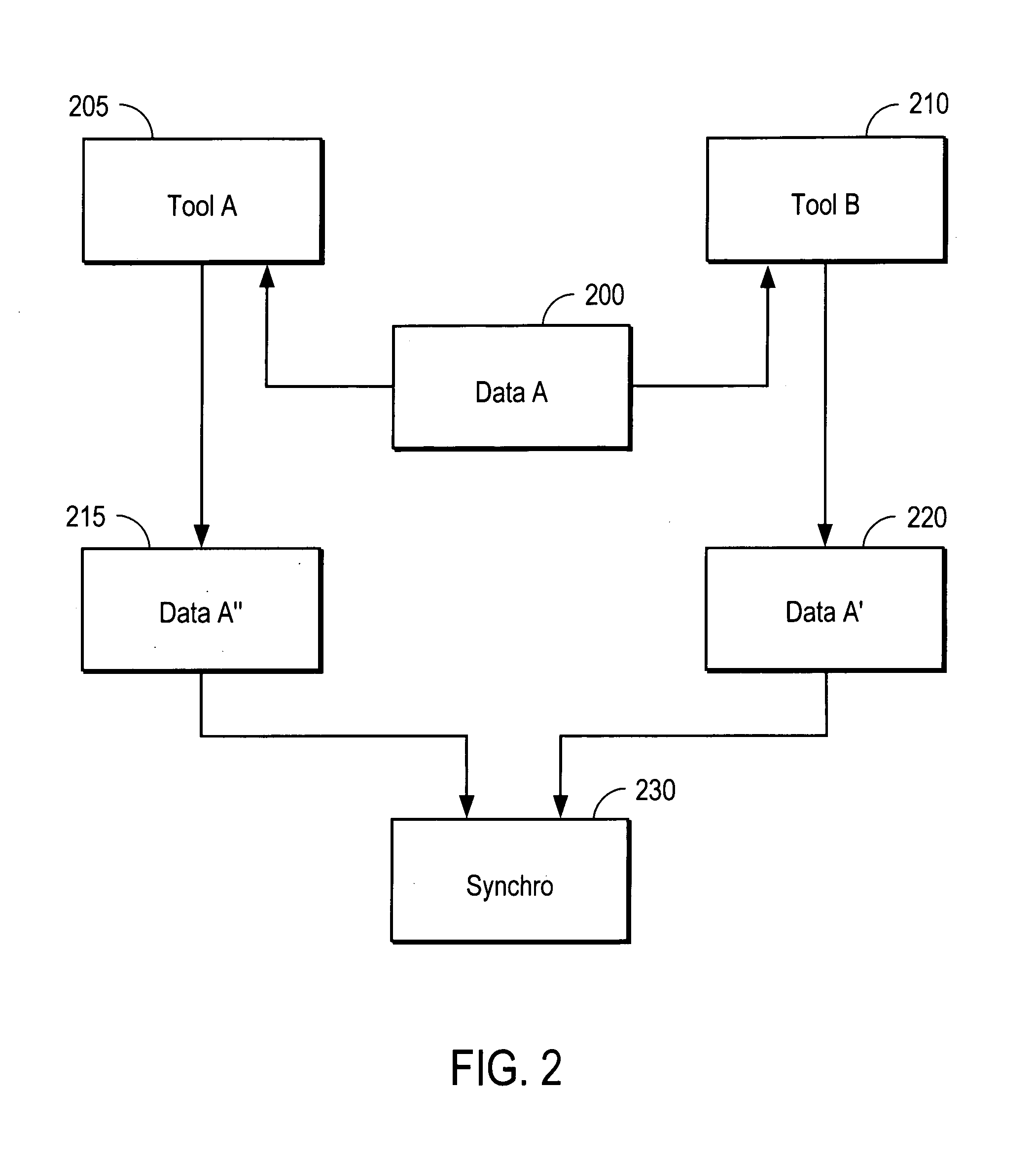
[0030]Referring again to the drawings, wherein like reference numerals designate identical or corresponding parts, and more particularly to FIG. 2 thereof, there is illustrated a block diagram of data flow illustrating different tool operations performed by different designer / users on a common data set. FIG. 2 represents one of many possible design iterations and modifications of design data. Design data 200 represents, for example, a first draft of a design produced by a first designer / user (e.g., user A). Data A is then used and modified by user A in Tool A 205. Tool A may be any design tool, such as a schematic capture tool, layout tool, any tool used to create or assign connectivity of the design, or may represent non-tool related modifications to Data A, resulting in a new data set Data A″215.

[0031]Data A 200 is also used by a separate design entity (e.g., user B), in a second tool, Tool B 210. Tool B 210 can be any design tool, such as a schematic capture tool, layout tool, an...


PUM


Abstract

Concurrent engineering among multiple design groups is facilitated by maintaining design changes in a data model of a design being developed. Design changes for each group are made from a baseline design. Changes are tracked by maintaining change information from all but an owner of the original baseline design. Changes are synchronized by identifying owner and non-owner changes and merging the changes to produce a final design. Since non-owner changes are tracked, the baseline design is not needed in synchronization. Preferably the invention is applied to electronic designs made by multiple design groups at geographically diverse locations. The invention may also be applied to any system where configuration management of developed software, parts, or any design is needed.

Description

COPYRIGHT NOTICE[0001]A portion of the disclosure of this patent document contains material which is subject to copyright protection. The copyright owner has no objection to the facsimile reproduction by anyone of the patent document or the patent disclosure, as it appears in the Patent and Trademark Office patent file or records, but otherwise reserves all copyright rights whatsoever.BACKGROUND OF THE INVENTION[0002]1. Field of Invention[0003]The present invention relates to design tools and coordination of engineering tasks between design tools. The invention is more particularly related to the coordination and synchronization of electronic design tasks between multiple tools and development activities.[0004]2. Discussion of Background[0005]As electronic design teams become geographically dispersed, there are changes in electronic design layout and logic that will inevitably occur concurrently. Even when designs are made in a single facility, concurrent changes are known to occur....

Claims


Application Information

Patent Timeline
IPC IPC(8): G06F15/00
CPCG06F17/50G06F30/00
Inventor KOHLI, VIKAS
Owner CADENCE DESIGN SYST INC
Why Eureka
Try Eureka