Apparatus and method for performing static timing analysis of an integrated circuit design using dummy edge modeling

a technology of integrated circuit design and static timing analysis, applied in the field of integrated circuits, can solve the problems of unduly pessimistic timing assumptions of einstimer and the integrated circuit design industry will have to spend excessive time manually analyzing circuits, and achieve the effect of reducing the workload of an integrated circuit designer

Inactive Publication Date: 2006-11-28
INT BUSINESS MASCH CORP
View PDF2 Cites 13 Cited by
  • Summary
  • Abstract
  • Description
  • Claims
  • Application Information

AI Technical Summary

Benefits of technology

[0008]An apparatus and method perform static timing analysis on an integrated circuit design. Certain pessimistic assumptions regarding slack when data launch and clock test signals are on opposite edges and derived from common logic blocks are improved by creating a dummy clock edge that is on the same edge as the data launch signal, and allowing the timing tool to compute the slack improvement using its native functions. The slack improvement is then multiplied by a conversion factor, and the result is used to adjust the slack. The apparatus and method give credit for slack in common blocks automatically, thereby allowing a large number of pessimistic slack values to be automatically corrected and reducing the workload of an integrated circuit designer in addressing the timing problems in an integrated circuit design.

Problems solved by technology

Static timing analysis generally takes into account best-case and worst-case delays of various circuit elements, thereby generating a list of problems that need to be corrected.
However, EinsTimer makes unduly pessimistic timing assumptions in some cases.
Without a mechanism for improving the pessimistic timing assumptions in known static timing tools, the integrated circuit design industry will have to spend excessive time manually analyzing circuits that are identified as a problem using a static timing tool.

Method used


Image

  • Apparatus and method for performing static timing analysis of an integrated circuit design using dummy edge modeling
  • Apparatus and method for performing static timing analysis of an integrated circuit design using dummy edge modeling
  • Apparatus and method for performing static timing analysis of an integrated circuit design using dummy edge modeling

Examples


Embodiment Construction

1.0 Overview

[0020]The present invention relates to static timing analysis of an integrated circuit design. For those not familiar with this subject, this Overview section will provide background information that will help to understand the present invention.

IBM EinsTimer

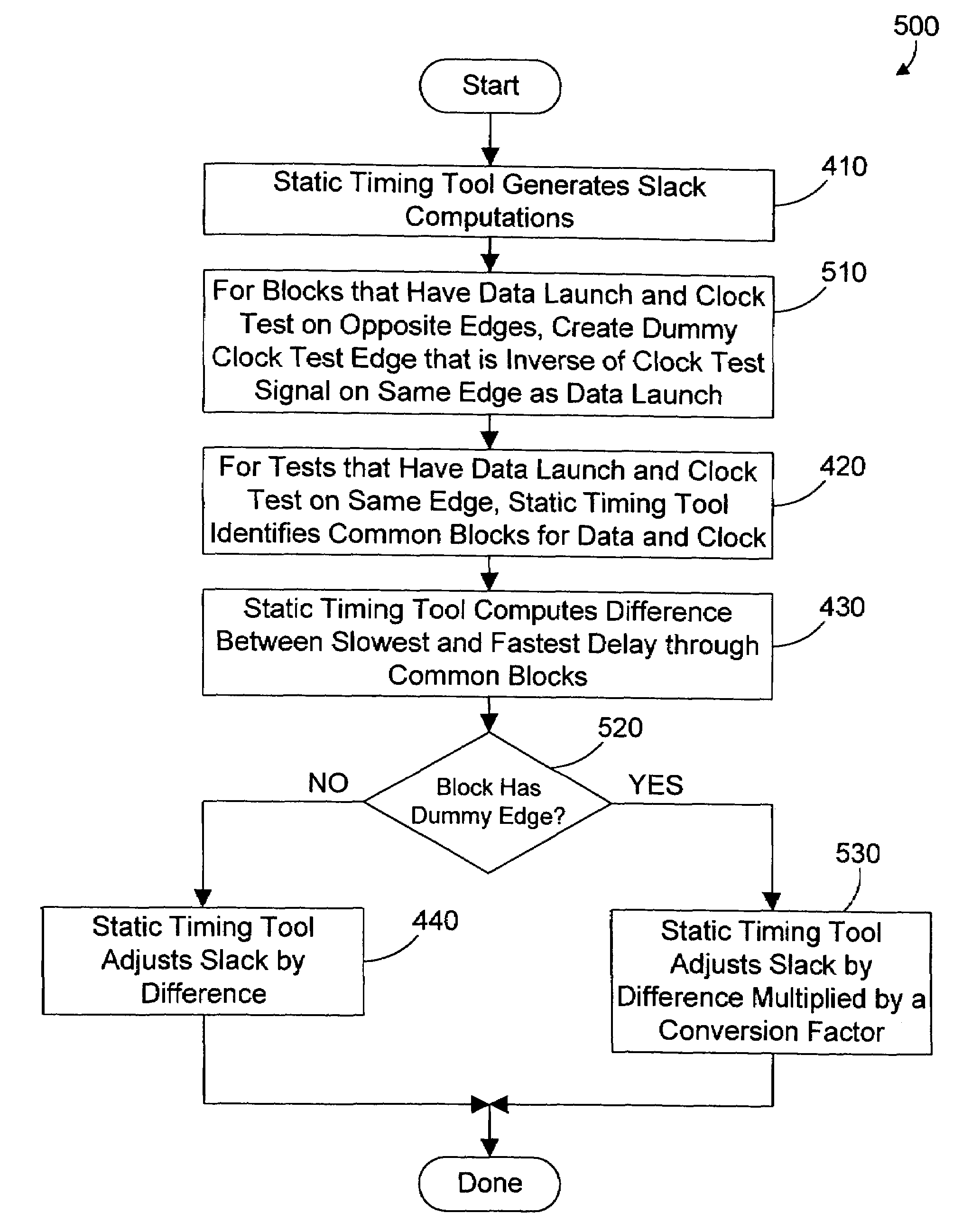
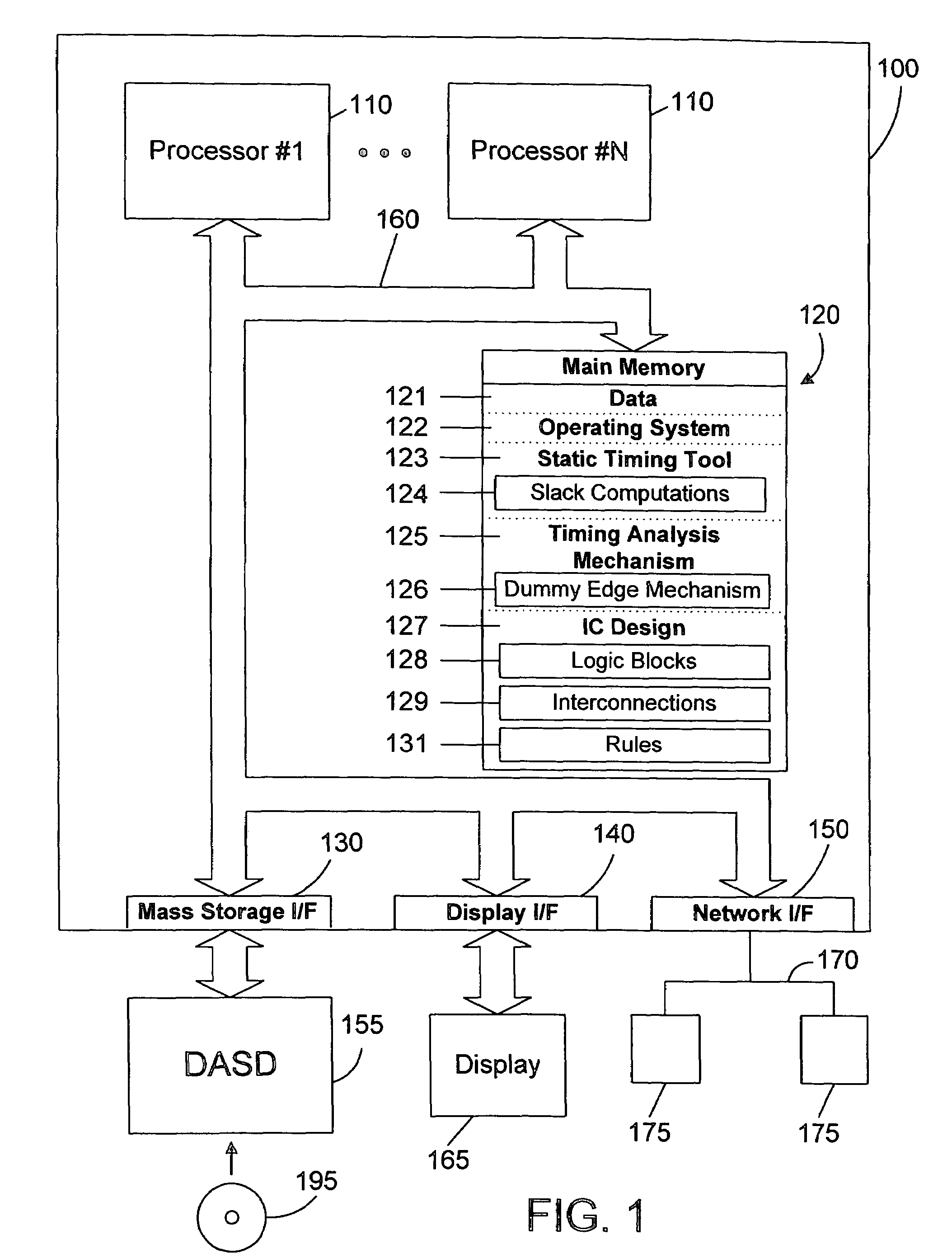
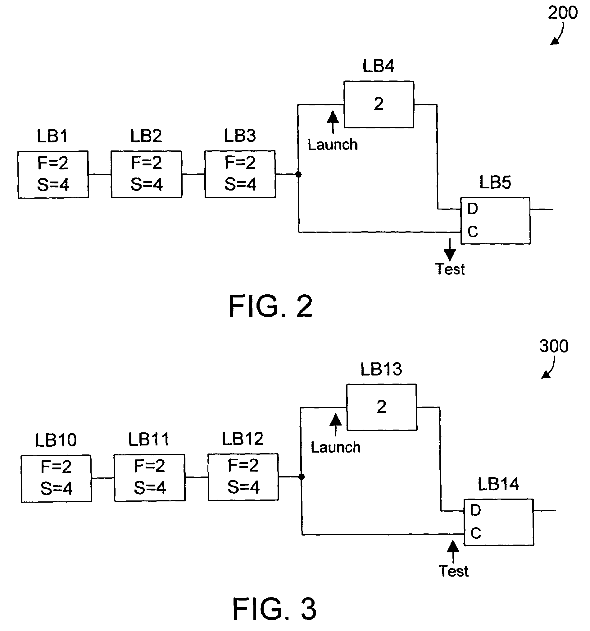
[0021]IBM developed a static timing tool known as EinsTimer. EinsTimer is used to automatically analyze the timing of an integrated circuit design at each node in the design. One specific analysis that EinsTimer performs is known as Linear Combination of Delays (LCD) analysis. LCD analysis allows modeling different amounts of delay in a set of logic blocks to generate worst-case timing scenarios. EinsTimer includes a feature known as Common Path Pessimism Removal (CPPR) that allows the tool to analyze the path for a clock test signal and a data launch signal and determine when both the clock test signal and data launch signal pass through a common block, and to give credit for the penalty imposed in the common blocks...


PUM


Abstract

An apparatus and method perform static timing analysis on an integrated circuit design. Certain pessimistic assumptions regarding slack when data launch and clock test signals are on opposite edges and derived from common logic blocks are improved by creating a dummy clock edge that is on the same edge as the data launch signal, and allowing the timing tool to compute the slack improvement using its native functions. The slack improvement is then multiplied by a conversion factor, and the result is used to adjust the slack. The apparatus and method give credit for slack in common blocks automatically, thereby allowing a large number of pessimistic slack values to be automatically corrected and reducing the workload of an integrated circuit designer in addressing the timing problems in an integrated circuit design.

Description

RELATED APPLICATION[0001]This patent application is related to a U.S. patent application “APPARATUS AND METHOD FOR PERFORMING STATIC TIMING ANALYSIS OF AN INTEGRATED CIRCUIT DESIGN”, Ser. No. 10 / 777,262 filed on Feb. 12, 2004 which is incorporated herein by reference.BACKGROUND OF THE INVENTION[0002]1. Technical Field[0003]This invention generally relates to integrated circuits, and more specifically relates to static timing analysis of integrated circuit designs.[0004]2. Background Art[0005]The proliferation of modern electronics is due in large part to the development of the integrated circuit. Integrated circuits allow many different circuit elements to be implemented on a single chip. As technology advances, the number of circuit elements on a chip of a given size increases, enhancing the performance and reducing the cost of integrated circuits.[0006]The design of integrated circuits is typically performed in three stages. The first stage is logic design, wherein the desired ope...

Claims


Application Information

Patent Timeline
Patent Type & Authority Patents(United States)
IPC IPC(8): G06F9/45G06F17/50
CPCG06F17/5031G06F30/3312
Inventor DARSOW, CRAIG MARSHALLOBERMILLER, TODD EDWARD
Owner INT BUSINESS MASCH CORP
Why Eureka
Try Eureka