
Power supply device for vehicle

a technology for power supply devices and vehicles, which is applied in the direction of battery/fuel cell control arrangements, cell components, instruments, etc., can solve the problems of reducing the dischargeable capacity of the battery included in and affecting the operation of the power supply device. to achieve the effect of suppressing the power consumption required

Inactive Publication Date: 2006-12-05
SANYO ELECTRIC CO LTD
View PDF18 Cites 32 Cited by
  • Summary
  • Abstract
  • Description
  • Claims
  • Application Information

AI Technical Summary

Benefits of technology

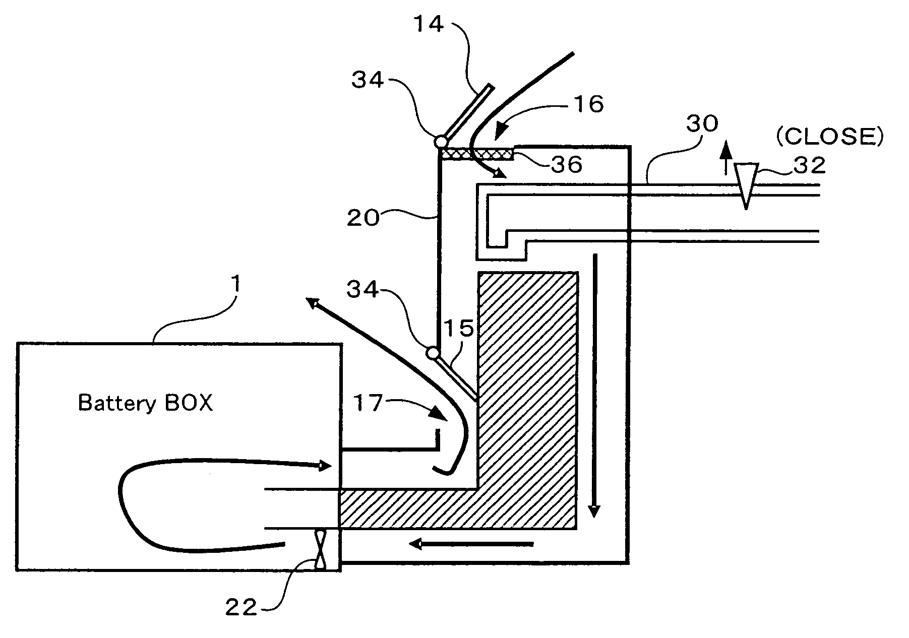
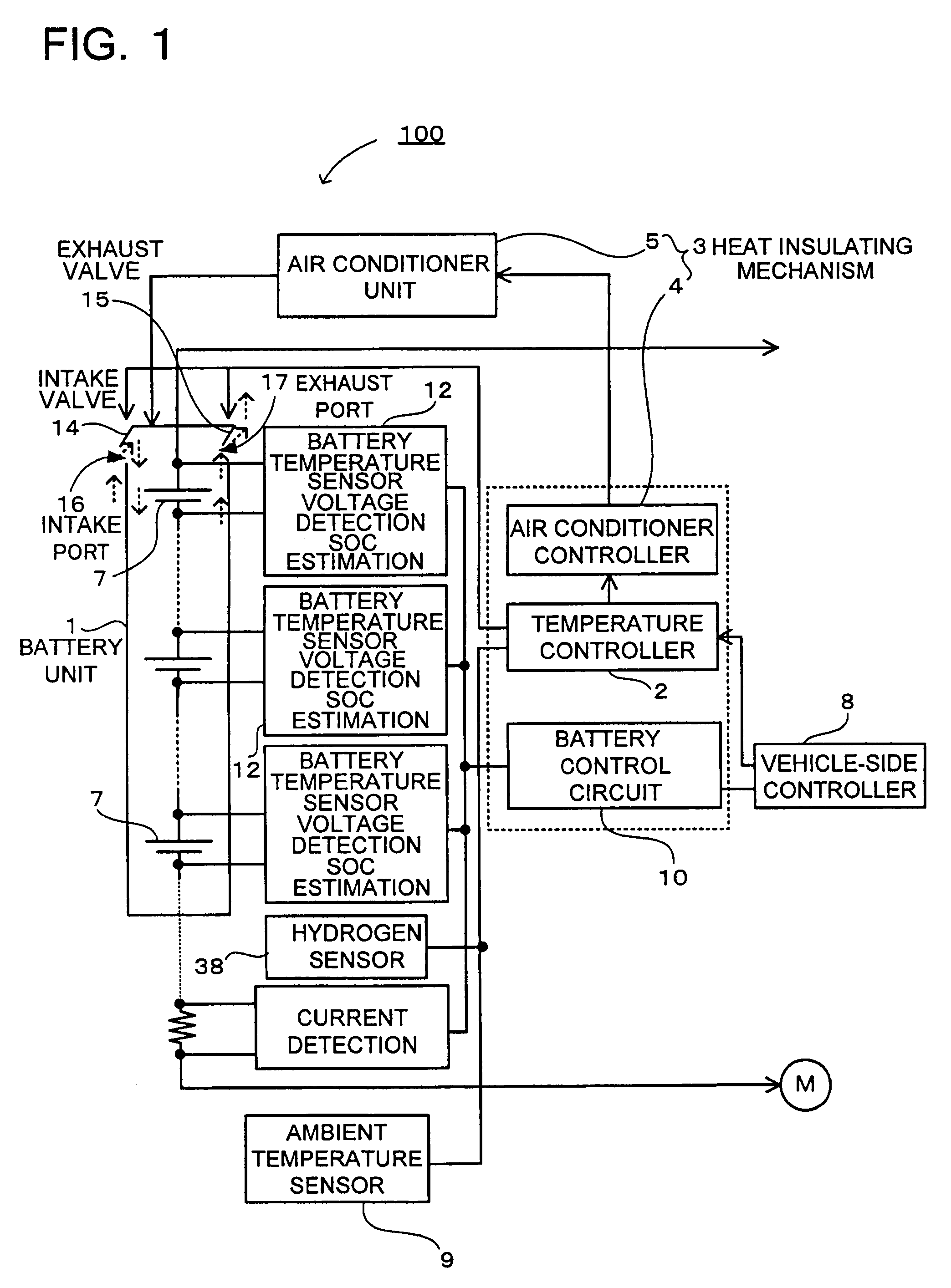
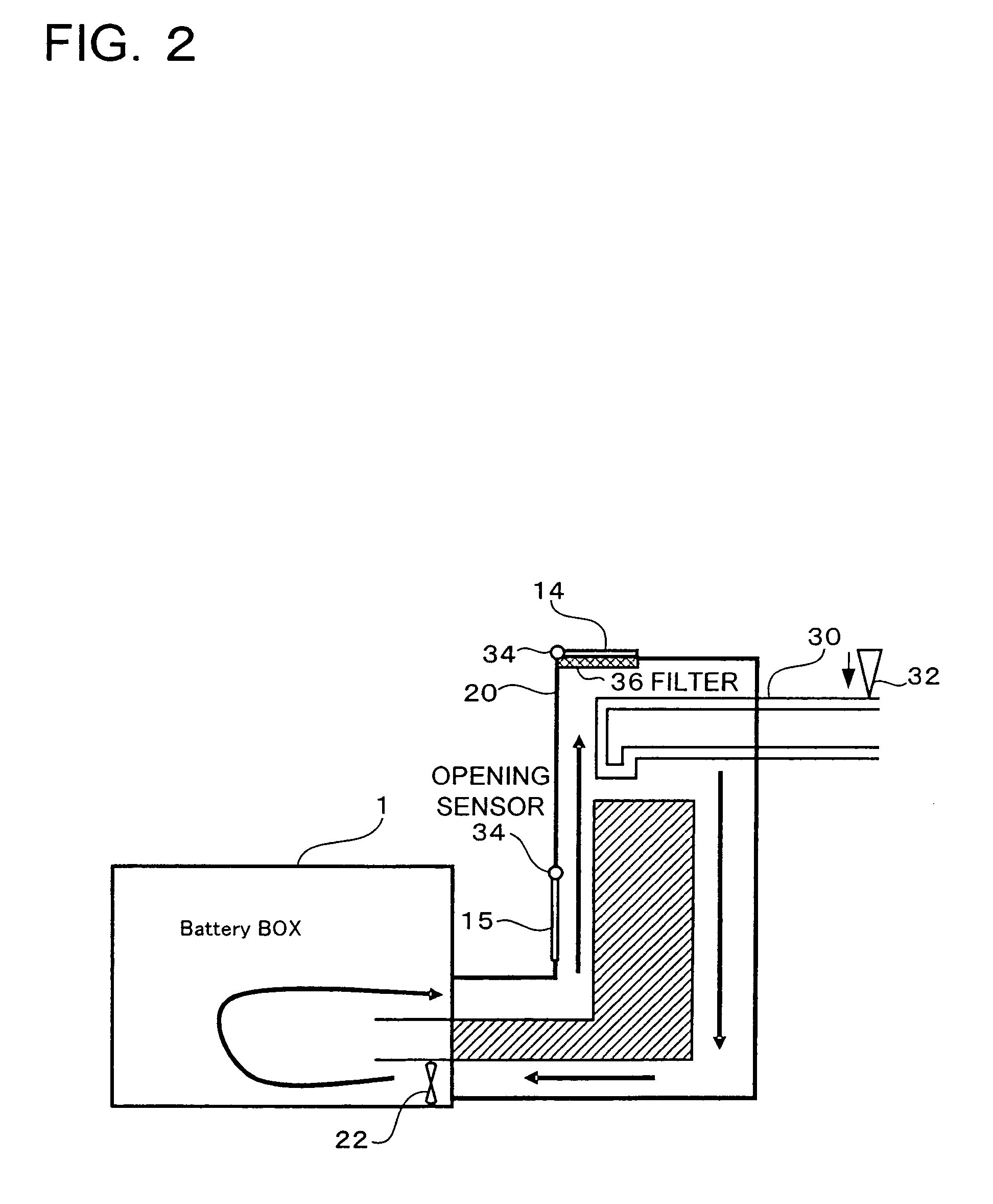
The present invention provides a power supply device for a vehicle that can efficiently control battery temperature and save energy by controlling the intake of outside air. The device includes a battery unit with a plurality of secondary batteries, a battery temperature sensor, a heat insulating mechanism, an outside air temperature sensor, an intake valve, an intake port, an intake valve, a temperature controller, an exhaust valve, an exhaust port, an opening sensor, a filter, and a hydrogen sensor. The device can also simultaneously control the temperature and air conditioning of the vehicle interior, improving fuel efficiency and energy efficiency.

Problems solved by technology

Vehicles such as an electric vehicle and a hybrid vehicle are used in extremely hostile temperature environment.
When the temperature is high and low, the electric performance of a power supply device built in a vehicle used in the environment deteriorates.
Specifically, when the temperature is low, the dischargeable capacity of a battery included in the power supply device decreases.
When a heat exchanger dedicated to a battery is provided to perform temperature control, however, the energy is consumed by the amount corresponding to the temperature control, and the use efficiency of the battery deteriorates.
However, the output of the air conditioner is consumed, not only for cooling the room, but also for cooling the battery, so that general power consumption of the air conditioner increases and the energy is consumed.
However, in this configuration as well, the power of the power supply device is consumed for controlling the temperature of the battery, so that the energy efficiency is low.

Method used


Image

  • Power supply device for vehicle
  • Power supply device for vehicle
  • Power supply device for vehicle

Examples


Embodiment Construction

[0025]Embodiments of the present invention will be described hereinbelow with reference to the drawings. The following embodiments relate to a power supply device for a vehicle for embodying the technical ideal of the present invention, and the present invention is not limited to a power supply device for a vehicle described below. Members in the scope of the claims are not limited to those shown in the particular embodiments. Some of the sizes, positions, relations, and the like of the members shown in the diagrams are exaggerated for clear description. In the following description, the same name and reference numeral are designated to the same or similar members, and their detailed description will not be repeated. Further, with respect to components of the present invention, a plurality of components may be constructed by the same members and one component may be used as a plurality of components. On the contrary, the function of one component may be realized by a plurality of co...


PUM

PropertyMeasurementUnit
temperatureaaaaaaaaaa

Abstract

A power supply device for a vehicle, for driving a motor which is mounted on a vehicle and makes the vehicle travel. The power supply device for a vehicle includes: a battery unit having a plurality of secondary batteries; a battery temperature sensor for detecting the temperature of a secondary battery; a heat insulating mechanism for controlling the temperature of the secondary battery; an outside air temperature sensor for detecting the temperature of air outside of the vehicle; an air intake port for taking the outside air to the battery unit in the vehicle; an intake valve for opening / closing the intake port; and a temperature controller for controlling the opening / closing of the intake valve on the basis of the temperature difference between the outside air temperature detected by the outside air temperature sensor and the battery temperature detected by the battery temperature sensor.

Description

BACKGROUND OF THE INVENTION[0001]1. Field of the Invention[0002]The present invention relates to a power supply device for driving a motor, which is mounted on a vehicle having a motor for making the vehicle travel and, more particularly, to a power supply device for a vehicle, for efficiently controlling temperature of a battery included in the power supply device.[0003]2. Description of the Related Art[0004]Vehicles such as an electric vehicle and a hybrid vehicle are used in extremely hostile temperature environment. In summer, a vehicle is exposed to the scorching sun and the temperature becomes extremely high. In the middle of winter or the like, the temperature becomes extremely low. When the temperature is high and low, the electric performance of a power supply device built in a vehicle used in the environment deteriorates. Specifically, when the temperature is low, the dischargeable capacity of a battery included in the power supply device decreases. On the other hand, when...

Claims


Application Information

Patent Timeline
Patent Type & Authority Patents(United States)
IPC IPC(8): F01P1/06B60K11/06H01M2/12H01M10/60H01M10/613H01M10/615H01M10/625H01M10/633H01M10/637H01M10/653H01M10/6556H01M10/6561H01M10/6563H01M10/6565H01M10/663
CPCH01M10/486H01M10/5004H01M10/5006H01M10/5016H01M10/5022H01M10/5024H01M10/5067H01M10/5095H01M10/625H01M10/615H01M10/633H01M10/663H01M10/6563H01M10/635H01M10/613B60L1/003B60L3/0084B60L2240/34B60L2240/545B60L2240/547B60L2240/549B60L2240/662B60L2260/44Y02T90/16B60L58/26B60L58/27B60L50/64Y02T10/70Y02T10/72Y02E60/10
Inventor HASHIZUMI, KAZUKISHIMIZU, HIDEO
Owner SANYO ELECTRIC CO LTD
Learn More