Construction machinery

a construction machinery and construction technology, applied in the direction of thinning machines, fluid couplings, electric control, etc., can solve the problems of not being able to achieve the torque, not being able to achieve the necessary driving torque in the hydraulic pump, and being far from the best, so as to achieve efficient generating of assisting torque. , the effect of high efficiency

Inactive Publication Date: 2006-12-05
KOMATSU LTD
View PDF11 Cites 22 Cited by
  • Summary
  • Abstract
  • Description
  • Claims
  • Application Information

AI Technical Summary

Benefits of technology

[0012]The present invention has been developed to solve the problems in the conventional technique described above. It is therefore an object of the present invention to provide construction machinery which is capable of improving fuel-consumption rate of the engine in the light-load mode (a mode where the engine torque at the intersection point of the iso-horsepower curve of the necessary horsepower and the governor characteristic curve of the engine 1 is smaller than that of the rating output point of the engine 1) and also capable of utilizing the surplus energy.
[0014]According to the construction machinery of this invention, in the load mode where the engine torque at the intersection point of the iso-horsepower curve of the necessary horsepower and the governor characteristic curve of the engine 1 is smaller than that of the rating output point of the engine 1, the number of revolutions of the engine is reduced, the engine torque is increased, and the engine is allowed to run with a horsepower exceeding the iso-horsepower curve. Therefore, the fuel consumption rate may usually be improved. This may provide excellent fuel consumption rate, so that the cost reduction can be achieved. Further, the power generator 11 is operated so as to generate electric power by the surplus torque, so that the generated electric power is accumulated in the power accumulation apparatus 12. With this structure, the surplus torque is effectively utilized and the machinery is highly economical.
[0016]According to the construction machinery of this invention, in the load mode where the iso-horsepower curve of the necessary horsepower and the governor characteristic curve of the engine 1 do not generate an intersection point, the engine 1 is driven at a point approximate to the rating output point while the power generator functioning as an electric motor is operated. Therefore, the necessary driving torque can be generated in the hydraulic pump 4, so that works corresponding to this load (for example, an excavation when the construction machinery is an hydraulic shovel) can be performed. Further, since the engine runs at a point approximate to the rating output point, shortage of the torque with reference to the necessary torque is small. Thus, the power generator 11 functioning as an electric motor and the power accumulation apparatus 12 can be miniaturized. Moreover, the operation of the power generator 11 can surely generate the torque for the shortage, so that the works corresponding to the high-load can be surely performed. Further, a driving torque necessary for the hydraulic pump 4 is not generated by the engine 1 alone in the case of the high-load mode. Therefore, it is possible to miniaturize the engine 1 and to achieve the reduced fuel consumption rate.
[0018]In the construction machinery of this invention, the power accumulation is performed with the number of revolutions by which the power generator is to be in the high efficiency state, so that the power accumulation can be performed efficiently.
[0020]In the construction machinery of this invention, the assist running is performed with the number of revolutions by which the power generator functioning as an electric motor is to be in the high efficiency state, so that the assisting torque can be generated efficiently.

Problems solved by technology

In this case, when the engine is simply miniaturized, there may arise a case that the necessary driving torque is not achieved in the hydraulic pump even when the capacity of the engine is 100% used.
In the conventional light-load mode described above, although the fuel-consumption efficiency is slightly improved, it is far from the best point.
Consequently, the electric motor needs larger output, which may result in that the torque is not achieved.
Moreover, the output of the engine has not been effectively utilized.

Method used


Image

  • Construction machinery
  • Construction machinery
  • Construction machinery

Examples


Embodiment Construction

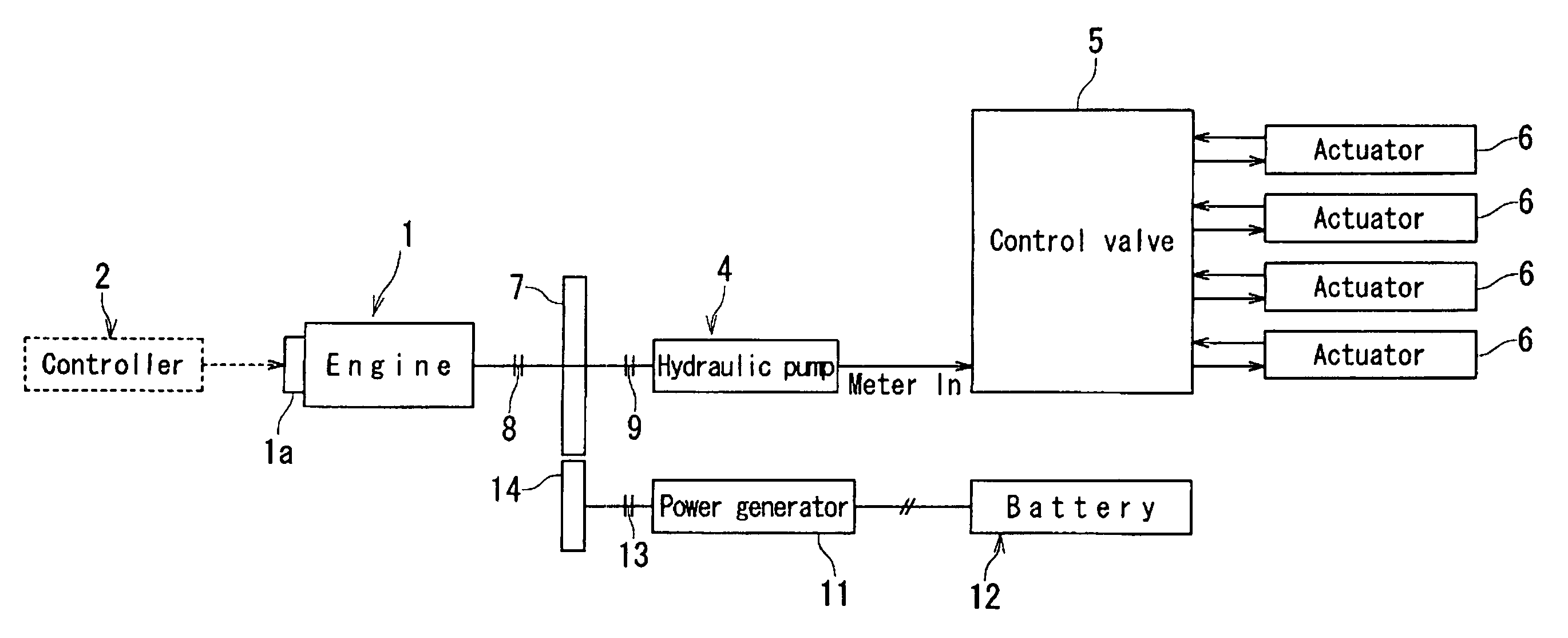
[0026]Next, a specific embodiment of construction machinery according to the present invention will be explained in detail with reference to the drawings. FIG. 3 is a schematic block diagram showing the driving system of construction machinery according to an embodiment of the present invention. In FIG. 3, the reference numeral 1 denotes the engine. The engine 1 is so configured that its number of revolutions is adjusted by a governor 1a, which receives a governor instruction from a controller 2. The numeral 4 denotes a hydraulic pump of the variable capacity type driven by the engine 1. Pressure oil discharged form the hydraulic pump 4 is supplied to various actuators 6 via a control valve 5. The actuators 6 may be a boom cylinder, an arm cylinder, a bucket cylinder, a right-side traveling motor, a left-side traveling motor, a turning motor and the like. The tilting angle of a swash plate of the hydraulic pump 4 is driven by a means for driving swash plate angle, not shown, which i...


PUM


Abstract

Construction machinery which is capable of improving fuel efficiency of the engine and also capable of effectively utilizing surplus energy in a light-load mode. The construction machinery includes an engine, a hydraulic pump driven by the engine, and actuators driven by oil pressure supplied from the hydraulic pump. In the light-load mode where the engine torque at the intersection point of an iso-horsepower curve of the necessary horsepower and a governor characteristic curve of the engine is smaller than that of a rated output point of the engine, the number of revolutions of the engine is reduced while the engine torque is increased with respect to the intersection point, and the horsepower is made to exceed the iso-horsepower curve. With surplus torque generated therefrom, a power generator is operated so as to generate electric power, which is stored in a power accumulation apparatus.

Description

BACKGROUND OF THE INVENTION[0001]1. Field of the Invention[0002]The present invention relates to construction machinery such as a hydraulic shovel.[0003]2. Description of the Related Art[0004]Conventional construction machinery is mainly of a hydraulic driving type. In a hydraulic shovel, for example, hydraulic actuators (hydraulic cylinder, hydraulic motor) allow a working machine to drive, a revolving superstructure to turn, and a lower traveling structure to travel. In the shovel, pressure oil is discharged from a hydraulic pump driven by the engine, and the pressure oil supplied to these hydraulic actuators is controlled, so that works are performed.[0005]Works of an hydraulic shovel do not always need to exhibit 100% of the capacity with reference to the capacity of the engine. Instead, there are many works which only need to exhibit 90% or 80% of the capacity. That is to say, as shown in the engine torque characteristic diagram shown in FIG. 4, there set working modes such as ...

Claims


Application Information

Patent Timeline
Patent Type & Authority Patents(United States)
IPC IPC(8): B60K17/356F02B41/00E02F9/20F02B63/06F02B75/02F02D29/00F02D29/04F02D29/06F02D45/00H02P9/04
CPCE02F9/2075E02F9/2217F02B41/00F02B63/06F02B75/02Y02P60/14
Inventor OHTSUKASA, NARITOSHI
Owner KOMATSU LTD
Why Eureka
Try Eureka