Hydraulic vehicle lift

a technology for lifting vehicles and lifts, applied in the direction of lifting devices, lifting equipment safety devices, transportation and packaging, etc., can solve the problems of limiting the access to moving parts during operation, reducing etc., to reduce the likelihood of the operator being injured, reduce the wear and tear of the lift parts, and improve the safety of the device

Inactive Publication Date: 2006-12-05
BIG D & LITTTLE D INVESTMENTS
View PDF22 Cites 29 Cited by
  • Summary
  • Abstract
  • Description
  • Claims
  • Application Information

AI Technical Summary

Benefits of technology

[0015]Importantly, because the cables are uniquely attached at the top center of each of the four columns, the weight of the vehicle on the ramps directs the force downward on each cable. There is no lateral pull on the cables and no side to side movement. This means that as the vehicle is being lifted, there is no shaking of the lift mechanism, as is common with the heretofore known vehicle lifts. The downward directional force on the cables also decreases wear on the lift parts and adds to the safety of the device.
[0016]Another advantage of the instant invention is that lifting parts, such as the cables, pulleys and lifting blocks on the cross members are all positioned within the columns. Further, cables, pulleys and hydraulics are positioned under the ramps. This placement of the working parts of the vehicle lift limits access during operation and decreases the likelihood of the operator becoming injured. Further, the placement of the parts limits exposure of the mechanical components to dirt and the environment, thereby increasing the life of the lift and improving operation. A flexible dust cover over the vertical slot in each column will further protect parts from dust and exposure and will also limit access to the moving parts during operation.
[0017]A lock latch located at the end of at least one of the cross members, can be manually inserted, via a lever, into one of several tabs fixed in the associated column. With a lock latch in place the ramps can not move downward. This locking arrangement increases safety and limits unintentional movement of the vehicle lift and further ensures that a vehicle on the lift will not be lowered in the event of failure of any of the moving parts.
[0018]For safety purposes, the vehicle lift has a tire block mounted at the front edge of both of the spaced-apart ramps. Additional tire blocks can be positioned on the back edge of each ramp after the vehicle is in place, to keep the vehicle from rolling backward off the ramps during, or after, elevation. Another feature of the device includes one or more movable drip trays which lay on an inner tray lip running the length of each of the ramps. The drip trays prevent fluids and debris from the elevated vehicle from damaging an underlying vehicle, or simply from making a mess on the floor. Also, a jack stand can be placed along the same inner tray lips. The jack stand allow a portion of the vehicle to be further elevated while on the vehicle lift, which facilitates working on the vehicle for example to change a tire or brakes. As it may be desirable at times to move the vehicle lift without removing the vehicle off of the ramps, casters can be pivotally mounted near the base of each of the spaced apart columns. The casters can be selectively engaged to allow movement of the lift, or stored off the ground to allow temporary fixed positioning of the lift.
[0019]An electrical contact shut off switch can be mounted within one or more of the four columns substantially adjacent the cable therein. When the platforms are elevated to the desired vertical position, the shut off switch will be slid to a point where it touches a portion of the cross member and is then fastened in place. When the cross member contacts the shut off switch during subsequent operation of the vehicle lift, the electric supply to hydraulic pump will be interrupted and vertical movement will stop. This is a particularly nice feature when using the vehicle lift to store a car in an area with limited height clearance. The vehicle can be lifted to its maximum height the first time, then when the shut off switch is positioned, the operator will not have to worry about lifting the car too high during subsequent elevations.

Problems solved by technology

This placement of the working parts of the vehicle lift limits access during operation and decreases the likelihood of the operator becoming injured.
A flexible dust cover over the vertical slot in each column will further protect parts from dust and exposure and will also limit access to the moving parts during operation.

Method used


Image

  • Hydraulic vehicle lift
  • Hydraulic vehicle lift
  • Hydraulic vehicle lift

Examples


Embodiment Construction

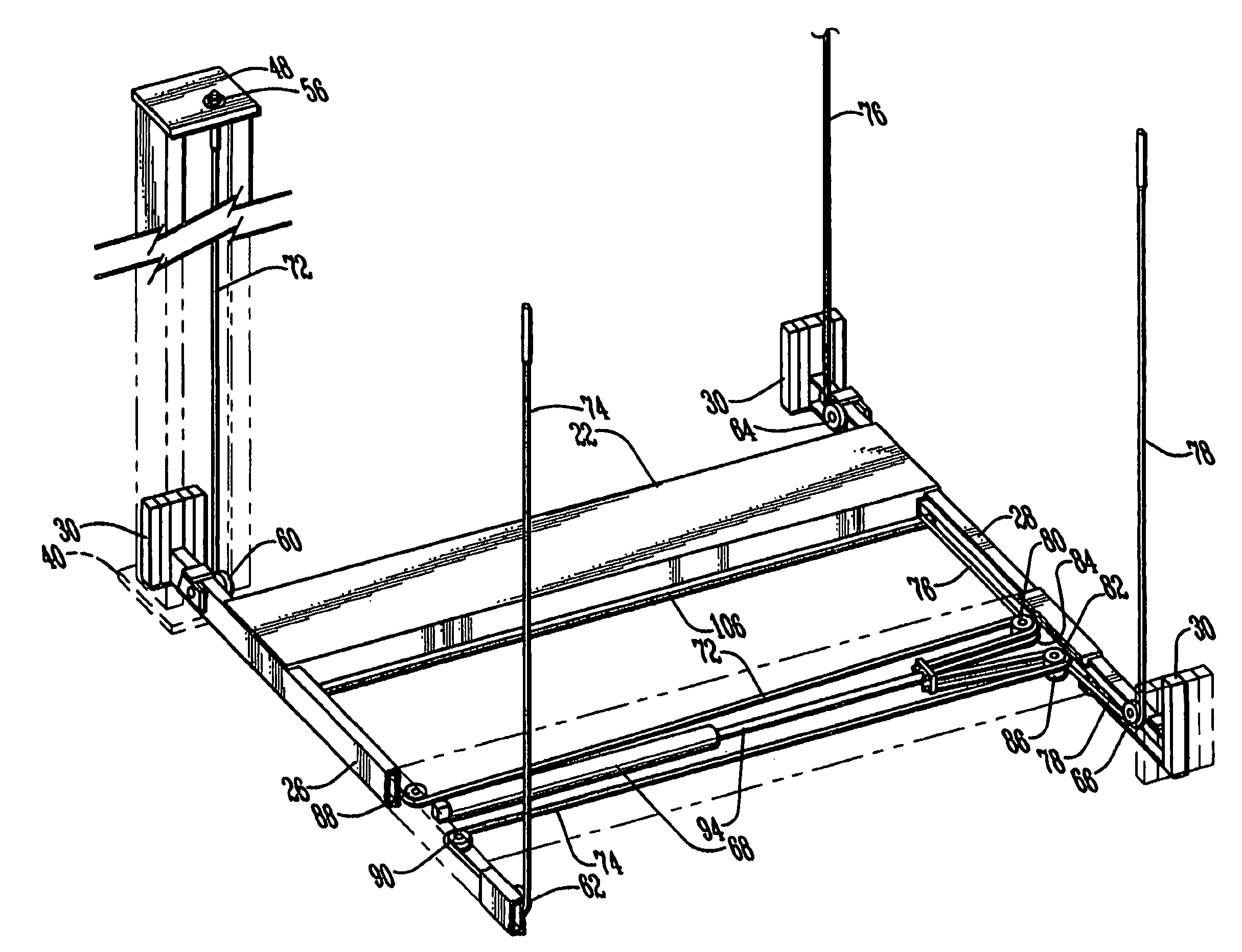
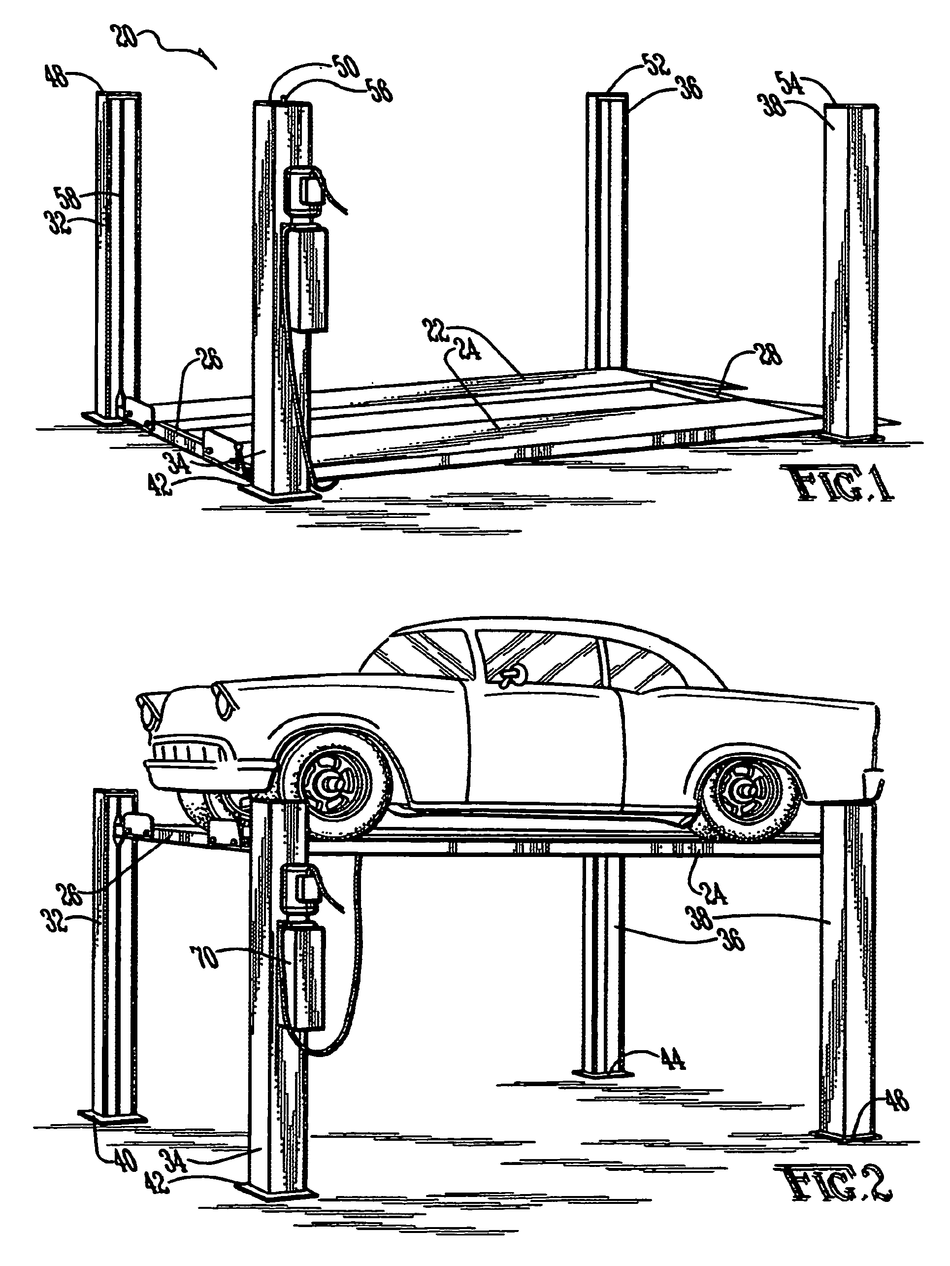
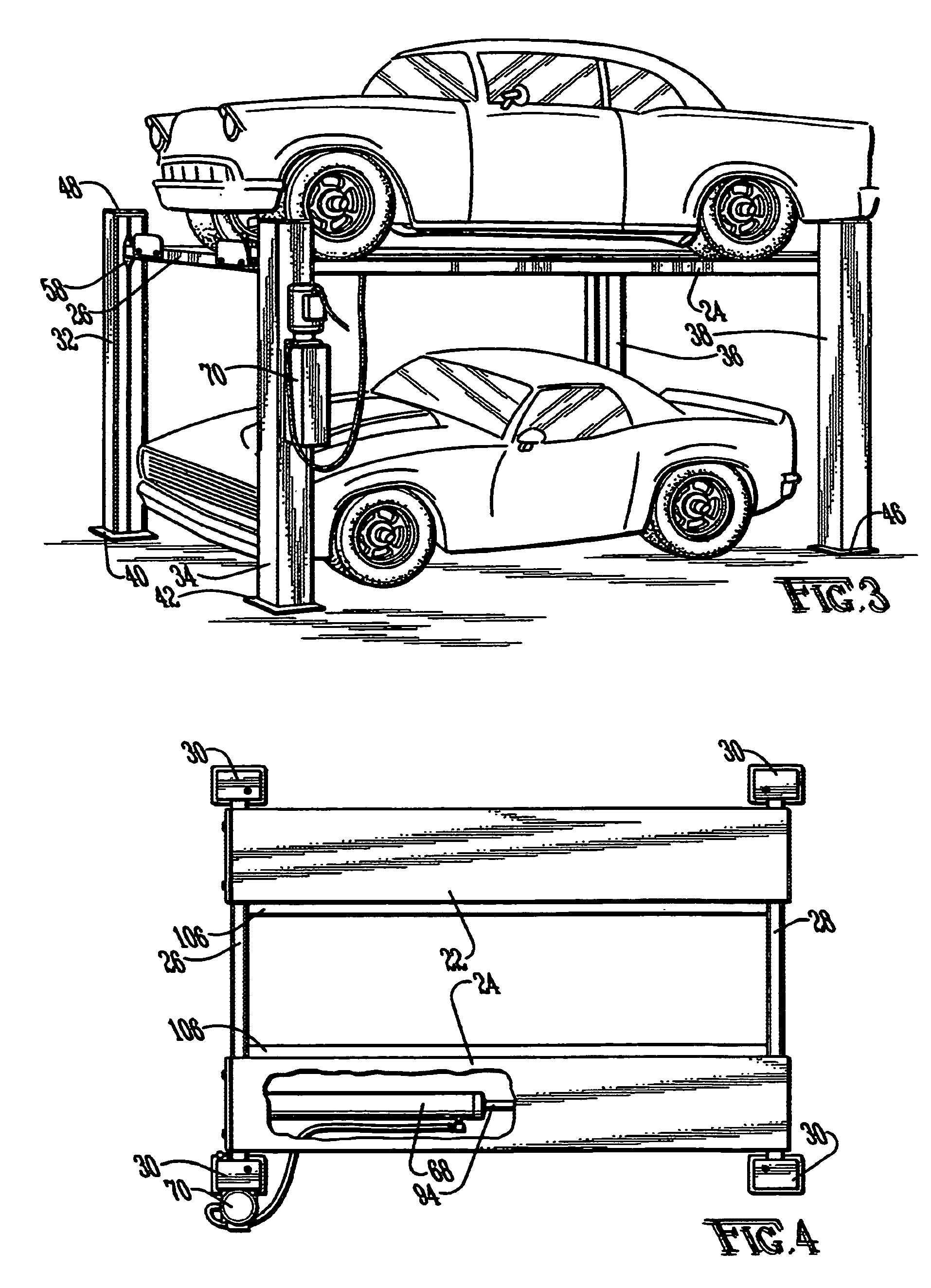
[0031]The present invention relates to a hydraulically operated vertical vehicle lift which allows for a person to work under the vehicle or for storing one vehicle over a second vehicle. The vehicle lift utilizes four large U-shaped columns positioned at each corner of the lift for stability and safety. A vehicle is elevated by a series of cables traversing through the U-shaped columns and around pulleys attached to cross members supporting the vehicle ramps. A hydraulic cylinder provides the lifting force. The orientation of the cables and pulleys direct the force, generated while elevating and suspending a vehicle, in a downward direction, as opposed to an angular direction, from the internal top center of each column. This directional force provides a stable vehicle lift and the columns and ramps shield the moving parts from operator contact and protect the parts from exposure thereby potentially increasing their useful life.

[0032]Referring now to the drawings in general, a vehi...


PUM


Abstract

A hydraulically operated vertical vehicle lift for working under the vehicle or for storing one vehicle over a second vehicle. The vehicle lift utilizes four large U-shaped columns which house most of the moving parts. Particularly, cables traverse through the columns and around pulleys attached to cross members supporting the vehicle ramps. A hydraulic cylinder under a ramp pulls the cables around the pulleys causing the cross members and ramps to elevate. The orientation of the cables and pulleys direct the force generated while elevating and suspending a vehicle straight down from the internal top center of each column. This directional force provides a stable vehicle lift and the columns and ramps shield the moving parts from operator contact and protect the parts from exposure thereby increasing their useful life of the lift.

Description

FIELD OF THE INVENTION[0001]Th present invention relates to an improved hydraulic vertical car lift which can be used to elevate a vehicle for servicing, repair or storage.BACKGROUND OF THE INVENTION[0002]Numerous prior art devices have been disclosed which are used for lifting a vehicle for servicing, repairing or storing vehicles. However, there are many problems inherent with the known lifting devices, such as safety, functionality and durability. Due to the size, weight and bulk of an automobile, lifting devices must be sturdy, reliable and safe.[0003]Devices commonly used to lift a vehicle for service or repair have a large, centrally positioned piston or ram, mounted in the floor or ground. When activated, the typical device will hydraulically lift the vehicle off the ground. These devices, while generally safe, limit accessibility to the underside of the lifted vehicle due to the size and central location of the piston.[0004]Another type of known vehicle lift is referred to a...

Claims


Application Information

Patent Timeline
Patent Type & Authority Patents(United States)
IPC IPC(8): B66F7/04
CPCB66F7/04B66F7/28B66F17/00
Inventor CHANCE, MITCH
Owner BIG D & LITTTLE D INVESTMENTS
Why Eureka
Try Eureka